


6. Solder a pair of leads to each motor, paying attention to the way the motor will eventually be oriented
in the chassis (see below). You might find it helpful to make a small bend at the tip of each lead to hook
into the hole in the motor lead tab to hold it in place for soldering.
Warning:
Holding the soldering iron against the motor lead for more than a few seconds can start
to damage the motor brushes, so try to be reasonably quick/efficient with this soldering. If the first
attempt does not go well, remove the soldering iron and let the motor cool for a few seconds before
trying again.
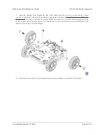
Each motor’s positive terminal is indicated by a plus sign (+) in the black plastic end of the motor. If you are
using one of our recommended micro metal gearmotors (
50:1
,
75:1
, or
100:1
) or any
lower
gear ratio, the motors
should be soldered into the main board with the positive terminal closest to the front, so you should attach the
leads to allow the motors to be oriented this way. However, if you are using a motor with a
150:1 or higher
gear
ratio, you should reverse the motor orientation so the positive terminals are facing the rear. (Don’t worry if you
accidentally get the orientation of one or both motors wrong, though. You can later correct for it in software with
our
Zumo32U4Motors library
[https://www.pololu.com/docs/0J63/6]
.)
Pololu Zumo 32U4 Robot User’s Guide
© 2001–2015 Pololu Corporation
4. Assembling the Zumo 32U4 kit
Page 35 of 76