background image

SprintScan 35LE Service Manual

        Troubleshooting

27

1. Unplug connector J7 and check the CCD module output signals.  Figure 3-4 shows

the pin designations for connector J7.

Note: The signals that drive the CCD module are outputted at connector J7 on the

main PC board.

Figure 3-4.  Pin assignment for connector J7

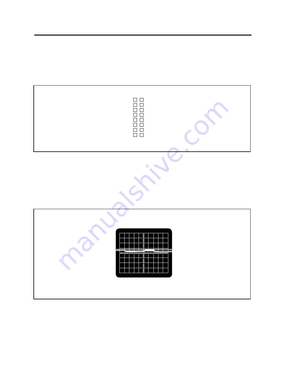
2. Check the CCD output signal at J7, Pin 16.   Figure 3-5 shows the correct output

waveform.

Note: If the output waveform is incorrect, replace the CCD module.

Figure 3-5. Preprocessing CCD Output Waveform at J7, Pin 16

OS

AGND

+12V

PHIR~

PHI1A~

DGND

PHI2A~

DOS

AGND

DGND

DGND

DGND

PHIX~

 +12V

 1

 3

 5

 7

 9

11

13

15

 2

 4

 6

 8

10

12

14

16

Summary of Contents for SS35 LE

Page 1: ...Repair Manual Americas Business Center Technical Services 201 Burlington Road Bedford MA 01730 TEL 1 781 386 5309 FAX 1 781 386 5988 SprintScan Slide Scanner SS35 LE September 1996 ...

Page 2: ... Scanner Fuses 16 Replacing System Fuse 16 Replacing Power Supply Fuse 17 Removing AC Inverter 18 3 Troubleshooting 19 Electrical Problems 19 Checking Power Supply Output Voltages 23 Checking for Short Circuit on Main PC Board 24 Checking Scanner Lamp 25 Checking CCD Module 26 Checking for Main PC Board Failure 28 Checking SCSI Port 28 Checking Filter Stepper Motor Malfunction 29 Checking Carriage...

Page 3: ...9 Chassis Assembly Mounting Screws 13 2 10 Filter Motor Assembly Alignment 14 2 11 Removing Power Supply 15 2 12 Replacing System Fuse 16 2 13 Replacing Power Supply Fuse 17 2 14 Replacing AC Inverter 18 3 1 Simplified Troubleshooting Diagram 19 3 2 Power Supply Output Connector J6 Pin Assignment 23 3 3 Pre Post Processing CCD Output Waveforms 26 3 4 Pin Assignment for Connector J7 27 3 5 Preproce...

Page 4: ... to shading in the original document In the second phase the analog signals are digitized The resulting binary codes stored in a video buffer and transmitted via the SCSI bus to the host Individual functional blocks are described in the following sections Photoelectric Converter The photoelectric converter Figure 1 2 consists of a light source lens and linear array CCD with associated driving circ...

Page 5: ... from the CCD is fed to this module and most of the scanned data processing is done in this stage The waveform output by the CCD is shown in Figure 1 3 where the magnitude of the output signal with respect to the bias voltage is a function of the intensity of the light incident upon the CCD Figure 1 3 CCD output waveform Since output signal bias voltage varies for different CCDs and output notches...

Page 6: ...n even when the input slide is uniformly white Calibration is used to compensate for this spatial variation Data Transfer Modules In the third phase of scanner operation the scanned data are transferred to the video ping pong buffer Then the data in the buffer are moved out to the host computer via the SCSI bus Command and Message Transfer The scanner accepts commands from and sends messages to th...

Page 7: ...een disconnected To prevent any chance of electric shock the SprintScan 35LE housing should only be opened by qualified service personnel and only after the scanner has been disconnected from the power source Care should be taken throughout all disassembly and reassemble procedures never to smudge or soil the lens or either mirror Removing Scanner Upper Housing 1 Turn off the power and disconnect ...

Page 8: ...y 8 3 Remove the scanner lamp Figure 2 2 Figure 2 2 Removing scanner lamp 4 Remove the four 4 screws Figure 2 3 securing the bottom case then remove the upper housing The latch of the base housing may fall off Figure 2 3 Removing upper housing ...

Page 9: ...ow these steps 5 Put the latch seated into its position close the upper housing align the tabs on the bottom of the upper housing with the slots at the front and rear of the bottom case snap the housing back on Figure 2 4 6 Then retighten the four 4 screws Figure 2 4 Installing upper housing ...

Page 10: ...ent Only use replacement lamps obtained from Polaroid or an authorized distributor Use of any other lamp may adversely affect scanning results 1 Turn off the power and disconnect the power cord 2 Remove the scanner lamp lid Figure 2 5 3 Replace the scanner lamp with a new one Figure 2 5 Removing scanner lamp Scanning Lamp Specifications Microtek Part Number 570 22 000004 Length Diameter Power Cons...

Page 11: ...urn off the power and disconnect the power cord 2 Remove the upper housing 3 Remove the four 4 screws securing the main PC board Figure 2 6 Figure 2 6 Removing main PC board 4 Disconnect all connectors and then lift out the main PC board Figure 2 7 Figure 2 7 Main PC board ...

Page 12: ...bly 12 5 Major component numbers are shown in Figure 2 8 Figure 2 8 Major component numbers J5 J6 J7 J3 J1 J2 To Carriage Motor To Filter Motor M 922 To Fan SCSI Interface SCSI ID SW1 To Voltage To Power Supply TP4 TP3 TP2 TP1 CCD Counector ...

Page 13: ...move the three 3 screws Figure 2 9 securing the chassis assembly 5 Lift out the chassis assembly Figure 2 9 Chassis assembly mounting screws 6 Remove the filter mount setscrew to remove the filter motor assembly Figure 2 10 from the chassis assembly Note Always refer to the Filter Motor Assembly Alignment procedure in Section 3 of this Service Manual when reinstalling chassis assembly Set screw 1 ...

Page 14: ...SprintScan 35LE Service Manual Disassembly 14 Figure 2 10 Filter assembly alignment Photo sensor ...

Page 15: ...move the upper housing 3 Remove the main PC board 4 Remove the chassis assembly 5 Remove the four 4 screws securing the power supply Figure 2 11 to the bottom case Figure 2 11 Removing power supply 6 Remove the power supply 7 Once the power supply is fixed replace it on the bottom case and tighten the four 4 securing screws ...

Page 16: ... two fuses installed in the SprintScan 35LE scanner one is located at the rear of the scanner and the other is located in the power supply Replacing System Fuse 1 Turn off the power and disconnect the power cord 2 Use a flat screw driver to lever over the fuse lid Figure 2 12 Figure 2 12 Replacing system fuse 3 Replace the fuse A spare fuse is located close to the rear side Fuse Specifications At ...

Page 17: ...y Fuse 1 Turn off the power and disconnect the power cord 2 Remove the scanner upper housing 3 Remove the main PC board 4 Remove the broken fuse Figure 2 13 and replace it with a new one Fuse rating 2 5A 250V or T2 5A 250V Europe Figure 2 13 Replacing power supply fuse ...

Page 18: ...nnect the four 4 cables connected to the scanning lamp Lift out the AC Inverter Note If applicable remove the broken fuse and replace it with a new one The AC Inverter fuse is soldered on the AC Inverter PC board In many cases problems may be solved by replacing 5 When fuse replacement is completed replace the AC Inverter on the bottom case and tighten the screw securing it to the bottom case Figu...

Page 19: ...ied block diagram indicating the types of electrical problems that may cause the scanner to malfunction The troubleshooting guide in Table 3 1 lists and describes each electrical problem that may cause the scanner to malfunction Table 3 1 also indicates the recommended corrective action that should be taken to repair the scanner Figure 3 1 Simplified troubleshooting diagram Power Failure Power Pro...

Page 20: ...placement procedure in Section 2 of this the Service Manual Note If replacing fuse does not correct the problem return scanner for repair Power supply Check power supply output voltages failure Refer to Power Supply test procedure in this Section of the Service Manual Short circuit on Refer to Short Circuit test procedure main PC board in this Section of the Service Manual Power LED Check for fail...

Page 21: ...re in the main PC board affects its output waveform Refer to Main PC Board test procedure in this Section of the Service Manual Scanner does not Check SCSI ID port Refer to respond to host Checking SCSI Port procedure in computer Start this Section of the Service Manual command Position sensor Note The position photo sensor failure mounted on the main PC board marked S1 is used to establish the fi...

Page 22: ... Possible Cause Corrective Action Carriage motor Position sensor Refer to Position Sensor test inoperative or failure procedure in this Section of the moves in wrong Service Manual direction Stepper motor Refer to Carriage Stepper Motor failure test procedure in this Section of the Service Manual ...

Page 23: ...n 2 and Pin 1 and Pin 6 of connector J6 4 Check each power supply output voltage Notes If J6 Pins 3 and 7 12V to J6 Pins 2 and 6 GND voltage is incorrect remove the AC inverter lamp driver connector on the power supply and then recheck J6 Pins 3 and 7 to J6 Pins 2 and 6 Replace the AC inverter if voltage is 12 VDC If any output voltage differs from the specifications by 5 or more replace the power...

Page 24: ... J3 J5 and J7 2 Power up the scanner and then measure all power supply output voltages Notes If any output voltage is incorrect replace the main PC board If the output voltages are correct proceed to step 3 3 Turn power off and then connect J7 4 Turn power on and then check voltage from connector J6 Pin 3 12 VDC to Pin 2 Power GND Note If voltage is incorrect replace the CCD module ...

Page 25: ...ace it 2 Check lamp to make certain it is correctly installed 3 Check voltage from J6 Pins 1 and 7 12 VDC to J6 Pins 2 and 6 GND Notes If the voltage is correct either the scanner lamp is faulty or burned out or the connector is faulty Replace either the lamp the connector or both If the voltage is incorrect check power supply If the lamp still does not light up after the lamp the connector and th...

Page 26: ...D module affects the CCD output waveform Figure 3 3 shows the preprocessing and the post processing CCD output waveform Figure 3 3 Pre Post processing CCD output waveforms PreprocessingCCDOutput Waveform at J7 Pin 16 4 8V 2 5 msec 64 msec Votage Time 0 Post processing CCD Output Waveform at TP1 ...

Page 27: ... are outputted at connector J7 on the main PC board Figure 3 4 Pin assignment for connector J7 2 Check the CCD output signal at J7 Pin 16 Figure 3 5 shows the correct output waveform Note If the output waveform is incorrect replace the CCD module Figure 3 5 Preprocessing CCD Output Waveform at J7 Pin 16 OS AGND 12V PHIR PHI1A DGND PHI2A DOS AGND DGND DGND DGND PHIX 12V 1 3 5 7 9 11 13 15 2 4 6 8 1...

Page 28: ... but the scanner does not respond to a Start Scanning commandfromthehostcomputer 1 Check to see if the SCSI ID is correct for both the software program and the scanner 2 Set the SCSI ID number to 7 and power up the scanner to enter the self test mode Shortly after the scanner carriage will traverse up and down at a slow speed Note If the scanner fails to perform this routine a main PC board malfun...

Page 29: ...or J3 then power up again 4 Check the voltage at connector J3 Pin 1 and Pin 6 Notes If the voltage is 5 VDC power has been correctly applied to position sensor Proceed to step 5 If the voltage is not 5 VDC replace the filter motor 5 Turn power off move the chassis away from carriage home position then power up 6 Check the voltage at connector J3 Pin 2 to see whether it changes continually Note If ...

Page 30: ...n at power up and before and after scanning Proper positioning ensures that scanning will not begin before the scanning window is within view of the CCD 1 Determine whether the position sensor is functioning properly by blocking the photo sensor scan with an opaque object 2 Turn power off and then move the chassis away from carriage home position 3 Turn power on Note If the carriage is still movin...

Page 31: ... J1 Pin 6 and 5 Notes If the voltage is not 12 VDC replace the carriage stepper motor If the voltage is 12 VDC power has been correctly applied to position sensor Proceed to step 4 4 Turn power off move the chassis away from carriage home position then power up again 5 Check the voltage at connector J1 Pin 1 to see whether it changes continually Notes If the voltage does not change continually rep...

Page 32: ...ignment of the CCD module or the lens Problems of focus and alignment can be most accurately analyzed by measuring CCD response at TP1 on the main PC board 1 Attach the scope s probe to TP1 and its ground line to TP4 Analog GND AGND 2 Disconnect the stepper motor power cable from connector J1 making sure that all other cables are connected and then power up the scanner 3 Rest the test slide on the...

Page 33: ...e 3 7 CCD response correct focus and alignment Oscilloscope Display Logic Analyzer Display Analog Waveform Trace Sample Period 5 s Start Trace 0000 ns After Trigger Single Trace Mode Immediate Trigger X O 0 0 mV 1 2 V 5 V ___________________________________ ...

Page 34: ...ignment Analog Waveform Trace Sample Period 5 s Start Trace 0000 ns After Trigger Single Trace Mode Immediate Trigger 4 V ___________________________________ X O 0 0 mV 1 2 V Analog Waveform Trace Sample Period 5 s Start Trace 0000 ns After Trigger Single Trace Mode Immediate Trigger 0 0 mV 1 2 V 5 V X O ___________________________________ ...

Page 35: ... return the old one to Polaroid for repair 1 With the scanner and oscilloscope set up as described in the preceding section loosen the lens setscrew and then break the contact adhesive holding the lens in place 2 Taking care not to touch the lens surface rotate the lens or move it in or out until the correct waveform is displayed 3 Holding the lens firmly in its new position with one hand tighten ...

Page 36: ... the linear bearing guide or lead is possibly in short of lubrication Lubricate the surface on both components be applying to the entire traversing range Note The recommended specification is API SF CC heavy duty motor oil This lubricant can be obtained from most gas stations The lubrication is only required for once a year or even longer ...

Reviews: