background image

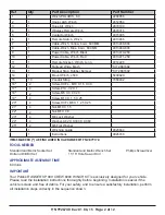
P/N 9926740  Rev 01  06/15   Page 11 of 12

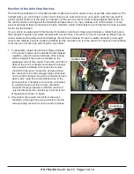
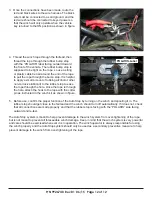
Function of the Auto Stop Feature:

The Auto Stop fairlead is an innovative solution making your winch easier to use, especially when plowing. The 

hardest work your winch does is when it isn’t doing much work at all; when your winch pulls the rope tight to 

get the last bit of lift out of the plow or to tighten up the hook to prevent it from rattling against the bumper. As 

the winch pulls the hook against the fairlead it stresses the winch, rope, fairlead, and vehicle frame. To help 

prevent damage to these components, Polaris created a solution that stops the winch before the hook is pulled 

too far into the fairlead.

If your vehicle is equipped with this feature it contains an aluminum Hawse-type fairlead, a rubber bump stop 

that contains magnets, and a wire harness with a control box. This winch is only for use with synthetic rope, as 

a steel cable would quickly wear and damage the aluminum fairlead. When the rubber bump stop is brought 

close to the fairlead, sensors inside the fairlead tell the control box to turn the winch off. The winch will continue 

to let rope out, but the rope will not pull in any further.

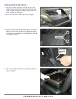
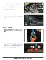
1.  To assemble, install the aluminum Hawse fairlead 

in the same location as the standard roller fairlead 

would be, using the same hardware. Wire routing 

will be simplest if the wires are located on the 

passenger side of the vehicle. Place the control box 

close to the winch contactor and extend the longer 

wire toward the fairlead. Disconnect the remote 

control from the winch contactor, and plug those 

two connectors into the corresponding connectors 

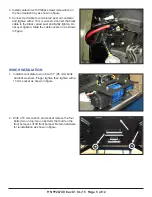
on the control harness. Once the connections have 

been made, route the red and black wires to the 

terminal block. The black wire must be connected 

to a solid ground, and the red wire should be 

connected to keyed power so that the winch will 

only operate when the vehicle key is turned to the 

ON position as shown in figure.

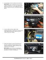
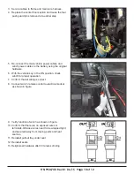
2.  Disconnect the remote control from the winch 

contactor, and plug those two connectors into the 

corresponding connectors on the control harness. 

Control Box

Connectors

Summary of Contents for RANGER XP 900 CREW 6000

Page 1: ...ese installation instructions for future reference and parts ordering information P N 2881668 RANGER XP 900 CREW 6000 WINCH KIT APPLICATION RANGER XP 900 CREW 18 6 NOTE You must order power cables sep...

Page 2: ...1 Hook Latch Winch 2412964 3 1 Rope Kit Winch 2879188 4 1 Wireless Remote Winch 2879316 5 1 Contactor Winch 4015095 6 1 Remote Switch Winch 4013466 7 1 Cable Winch Yellow 6 GA 800 MM 4013468 800 8 1...

Page 3: ...from battery Disconnect red positive cable from battery 2 Remove hood from vehicle as shown in figure 3 Remove four push darts fasteners from center floor section One on each side by foot pedal as sho...

Page 4: ...es through the tunnel area under the rear floor section and into the area under the rear seat 2 Slide the other end of cable through bulkhead Follow main wire harness up and onto the splash tray as sh...

Page 5: ...the black coded post and lightly tighten Do not over tighten Slide the cable covers on as shown in figure WINCH INSTALLATION 1 Install mount plate to winch with 1 25 mm bolts and lock washers Finger...

Page 6: ...figures 4 Connect yellow and blue cables to the corresponding post on winch with a 10 mm wrench Push cables up through the splash tray and to contactor as shown in figure 5 Install roller fairlead or...

Page 7: ...n wrench and 15mm socket as shown in figures 8 Connect the yellow and blue winch wires to contactor and push cable covers on as shown in figure 7 Reinstall front bumper with fastener removed earlier M...

Page 8: ...must be removed by cutting along the perimeter scribe line with a sharp tool Remove the round plastic cut out as shown in figure 3 Install the grommet PN 5414440 IMPORTANT Vehicle hardware kit contai...

Page 9: ...of moving parts and panduit to frame 5 Push the wires back through the grommet and replace grommet in upper splash tray hole Connect black wire to connector and red wire to the keyed power terminal Af...

Page 10: ...13 Retighten all hardware after 30 minutes of riding 5 Re connect the main vehicle power cables and winch power cables to the battery using the original hardware 6 With the vehicle key in the ON posi...

Page 11: ...n the rubber bump stop is brought close to the fairlead sensors inside the fairlead tell the control box to turn the winch off The winch will continue to let rope out but the rope will not pull in any...

Page 12: ...ad and the winch should turn off automatically If it does not check that all connections are made properly and that the rubber stop is facing with the POLARIS side facing outward and re test The Auto...

Reviews: