


P/N 9926740 Rev 01 06/15 Page 9 of 12
FINAL INSTALLATION:
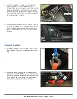
1. Auto Stop Fairlead:
Slide on rubber stop, Polaris
logo showing. Attach winch hook with cotter pin to
rope.
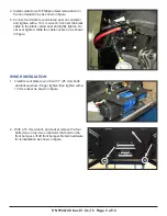
2. Attach red cables to battery to the battery side of
starter solenoid. Attach black ground wire to ground
post. After wires are connected, panduit power and
ground cables to the main wire harness to keep
clear of moving parts and panduit to frame.
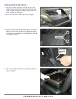
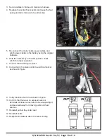
5. Push the wires back through the grommet and
replace grommet in upper splash tray hole.
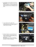
Connect black wire to connector and red wire to the
keyed power terminal. After wires are connected,
panduit power and ground cables to the main wire
harness to keep clear of moving parts and panduit
to frame as shown in figure.
6. Attach switch with the two Phillips screws, washers
and nuts provided in kit. Install in this order, screws,
switch housing, dash, washer, nut. Tighten with a
Phillips screwdriver and a 8 mm wrench as shown
in figure.
Grommet


