ELECTRICAL
10.13
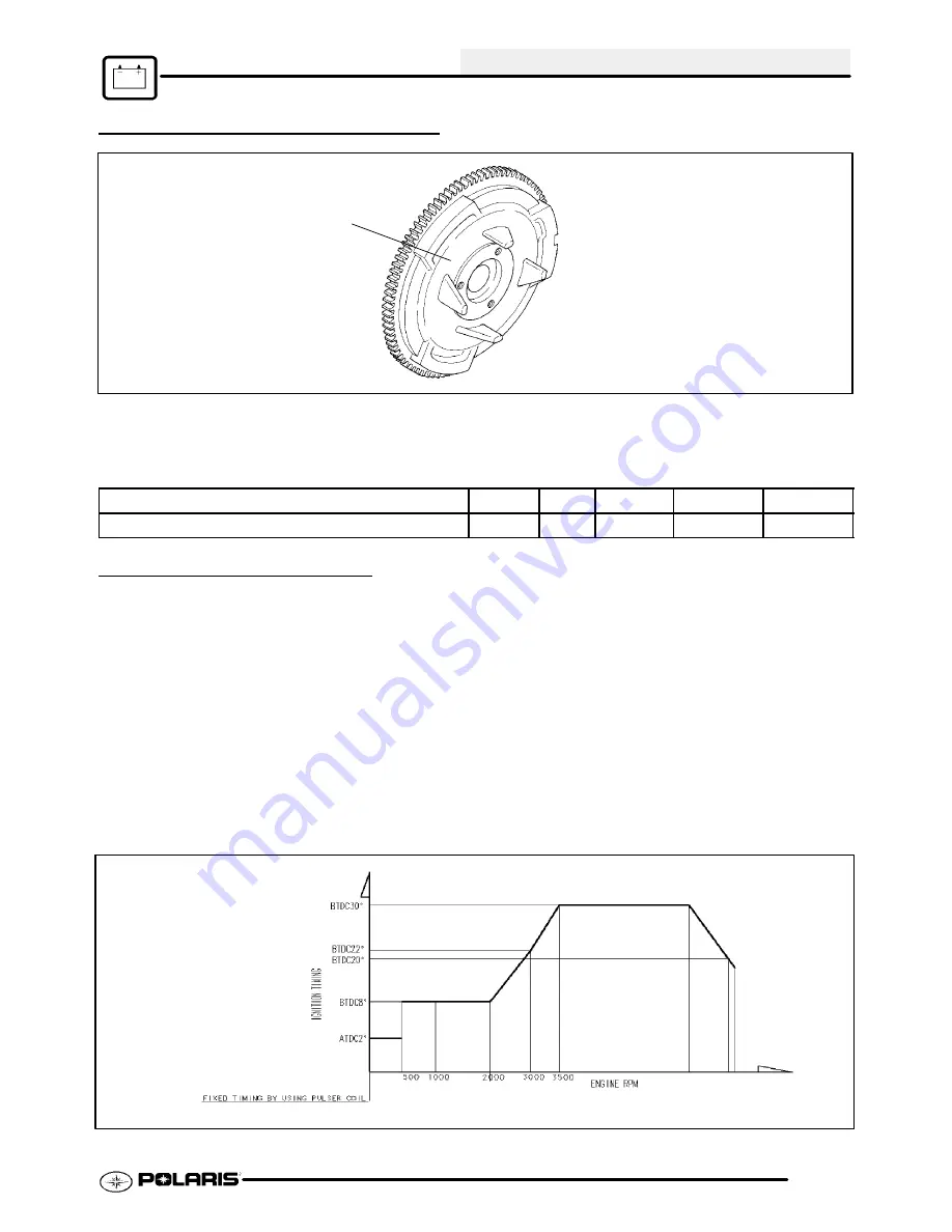
FLYWHEEL IDENTIFICATION
A
Flywheel Identification Stamp Location
The flywheel can be identified by the stamp mark in location A. Refer to “I.D.” location in chart below. Do not
use the cast mark to determine flywheel application.
Engine Application
Type
Cast
Stamp
Comment
I.D. Stamp
ES32PFE
N/A
N/A
N/A
210W
N/A
330 -- DC/CDI IGNITION
The Trail Boss 330 has incorporated into it’s design a
DC/CDI ignition system.
Some of the advantages of DC ignition are:
G
Stronger, more consistent spark at low
rpm for better performance
G
Easier starts
G
Simpler component design for ease
trouble shooting and maintenance
Operation Overview:
The DC/CDI system relies on battery power for ignition.
Instead of generating DC voltage via magnetic
induction, a 12 volt DC current is supplied directly to the
CDI unit from the battery.
At the CDI, 12 volt DC current charges an internal
capacitor to build up the initial ignition charge. A small
A/C signal from the Trigger (Pulse) coil closes a
thyristor
(located
in
the
CDI)
at
a
point
pre--determined in the crankshaft rotation by magnets
on the flywheel’s outer diameter. This signal releases
the electrical charge which saturates the coil for
ignition. DC/CDI systems have the ability to ignite
with as little as 6 volts of power.
Typical Timing Curve Shown
NOTE:
DC/CDI systems and compo-
nents are not interchangeable
with any other system.
PartShark.com
877-999-5686
Summary of Contents for 2009 Trail Blazer 330
Page 94: ...ENGINE 3 48 NOTES P a r t S h a r k c o m 8 7 7 9 9 9 5 6 8 6 ...
Page 110: ...FUEL SYSTEM CARBURETION 4 16 NOTES P a r t S h a r k c o m 8 7 7 9 9 9 5 6 8 6 ...
Page 124: ...BODY STEERING SUSPENSION 5 14 NOTES P a r t S h a r k c o m 8 7 7 9 9 9 5 6 8 6 ...
Page 196: ...ELECTRICAL 10 4 REVERSE LIMIT SYSTEM P a r t S h a r k c o m 8 7 7 9 9 9 5 6 8 6 ...
Page 226: ...ELECTRICAL 10 34 NOTES P a r t S h a r k c o m 8 7 7 9 9 9 5 6 8 6 ...
Page 227: ...ELECTRICAL WIRING DIAGRAM 2009 TRAIL BOSS P a r t S h a r k c o m 8 7 7 9 9 9 5 6 8 6 ...
Page 228: ...ELECTRICAL WIRING DIAGRAM 2009 TRAIL BOSS P a r t S h a r k c o m 8 7 7 9 9 9 5 6 8 6 ...
Page 229: ...ELECTRICAL WIRING DIAGRAM 2009 TRAIL BLAZER P a r t S h a r k c o m 8 7 7 9 9 9 5 6 8 6 ...
Page 230: ...ELECTRICAL WIRING DIAGRAM 2009 TRAIL BLAZER P a r t S h a r k c o m 8 7 7 9 9 9 5 6 8 6 ...


