ELECTRICAL
10.25
CONVENTIONAL BATTERY
OFF SEASON STORAGE
To prevent battery damage during extended periods
of non-use, the following basic battery maintenance
items must be performed:
G
Remove the battery from the machine
and wash the case and battery tray
with a mild solution of baking soda
and water. Rinse with lots of fresh
water after cleaning. NOTE: Do not
get any of the baking soda into the
battery or the acid will be neutralized.
G
Using a wire brush or knife, remove any
corrosion
from
the
cables
and
terminals.
G
Make sure that the electrolyte is at the
proper level. Add distilled water if
necessary.
G
Charge at a rate no greater than 1/10 of
the battery’s amp/hr capacity until
the
electrolyte’s
specific
gravity
reaches 1.270 or greater.
G
Store the battery either in the machine
with the cables disconnected, or
store in a cool place.
NOTE: Stored batteries lose their charge at the rate
of 1% per day. Recharge to full capacity every 30 to
60 days during a non-use period. If the battery is
stored during the winter months, electrolyte will freeze
at higher temperatures as the battery discharges.
The chart below indicates freezing points by specific
gravity.
Electrolyte Freezing Points
Specific Gravity
of Electrolyte
Freezing
Point
1.265
-75
°
F
1.225
-35
°
F
1.200
-17
°
F
1.150
+5
°
F
1.100
+18
°
F
1.050
+27
°
F
CONVENTIONAL BATTERY
CHARGING PROCEDURE
1.
Remove the battery from the ATV to prevent
damage from leaking or spilled acid during
charging.
2.
Charge the battery with a charging output no
larger than 1/10 of the battery’s amp/hr rating.
Charge as needed to raise the specific gravity to
1.270 or greater.
3.
Install battery in vehicle with positive terminal
toward the front. Coat threads of battery bolt with
a corrosion resistant dielectric grease.
Dielectric Grease
(PN 2871329)
4.
Connect battery cables.
WARNING!:
To avoid the possibility of sparks and/or
explosion, connect positive (red) cable first and
negative (black) cable last.
5.
After connecting the battery cables, install the
cover on the battery and attach the hold down
strap.
6.
Install clear battery vent tube from vehicle to
battery vent. WARNING: Vent tube must be free
from obstructions and kinks
and securely
installed. If not, battery gases could accumulate
and cause an explosion. Vent should be routed
away from frame and body to prevent contact with
electrolyte. Avoid skin contact with electrolyte, as
severe burns could result. If electrolyte contacts
the vehicle frame, corrosion will occur.
7.
Route cables so they are tucked away in front and
behind battery.
8.
Reinstall battery, attaching positive (+) (red) cable
first and then the negative (-) (black) cable. Coat
terminals and bolt threads with Dielectric Grease
(PN 2871329).
9.
(Conventional Lead/Acid Batteries Only) Install
clear battery vent tube from vehicle to battery vent.
WARNING:
Vent tube must be free from
obstructions and kinks and securely installed. If not,
battery gases could accumulate and cause an
explosion. Vent should be routed away from frame
and body to prevent contact with electrolyte. Avoid
skin contact with battery electrolyte, severe burns
could result.
If electrolyte contacts the vehicle
frame, corrosion will occur.
10. Route cables so they are tucked away in front and
behind battery.
11. Reinstall battery cover and holder strap.
PartShark.com
877-999-5686
Summary of Contents for 2009 Trail Blazer 330
Page 94: ...ENGINE 3 48 NOTES P a r t S h a r k c o m 8 7 7 9 9 9 5 6 8 6 ...
Page 110: ...FUEL SYSTEM CARBURETION 4 16 NOTES P a r t S h a r k c o m 8 7 7 9 9 9 5 6 8 6 ...
Page 124: ...BODY STEERING SUSPENSION 5 14 NOTES P a r t S h a r k c o m 8 7 7 9 9 9 5 6 8 6 ...
Page 196: ...ELECTRICAL 10 4 REVERSE LIMIT SYSTEM P a r t S h a r k c o m 8 7 7 9 9 9 5 6 8 6 ...
Page 226: ...ELECTRICAL 10 34 NOTES P a r t S h a r k c o m 8 7 7 9 9 9 5 6 8 6 ...
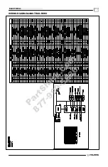
Page 227: ...ELECTRICAL WIRING DIAGRAM 2009 TRAIL BOSS P a r t S h a r k c o m 8 7 7 9 9 9 5 6 8 6 ...
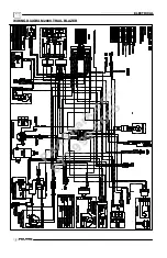
Page 228: ...ELECTRICAL WIRING DIAGRAM 2009 TRAIL BOSS P a r t S h a r k c o m 8 7 7 9 9 9 5 6 8 6 ...
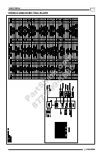
Page 229: ...ELECTRICAL WIRING DIAGRAM 2009 TRAIL BLAZER P a r t S h a r k c o m 8 7 7 9 9 9 5 6 8 6 ...
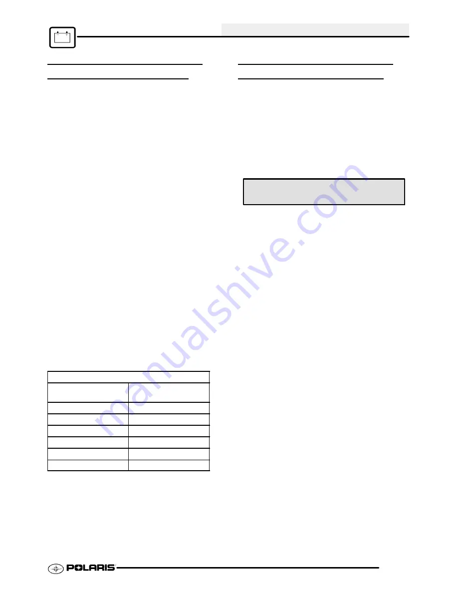
Page 230: ...ELECTRICAL WIRING DIAGRAM 2009 TRAIL BLAZER P a r t S h a r k c o m 8 7 7 9 9 9 5 6 8 6 ...


