background image

User manual                                                   HANDY TERMINAL


35


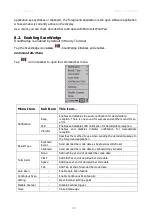
BLUE + 5


Increase screen brightness 

BLUE + 6


Increase volume 

BLUE + 8


Decrease screen brightness 

BLUE + 9


Decrease volume 

BLUE + 0 

Delete 

BLUE + SP 

Align the screen 
(Press ESC to exit) 

BLUE + Start 

Enter suspend mode 


The keypad is color-coded in blue to indicate these key combinations. 


NOTE: 

The color-coded indicators are located 

upper 

each key.


5.7.


RED Key Combinations 

RED key modifies the next key pressed to type specific characters. 


Key Combination


Function


RED + 1


RED + 2


RED + 3


RED + 4


RED + 5


RED + 6


RED + 7


RED + 8


RED + 9


RED + . 

- (minus) 

RED + 0 

RED + SP 

+ (plus) 


The keypad is color-coded in yellow to indicate these key combinations. 


NOTE: 

The color-coded indicators are located


upper 

each key. 

5.8.


Program Buttons 


Buttons can be programmed to execute different functions using the Program Button program in the 
Control Panel. The following buttons on the HANDY TERMINAL are programmed for the listed 
function. Press and hold BLUE key and press the appropriate function key to execute the indicated 
function. 

Summary of Contents for HT-K10-SC

Page 1: ......

Page 2: ...ndicators 13 3 4 Guidelines for Battery Pack Use and Disposal 13 3 5 Turn Your Device On 14 3 6 Desktop 14 3 7 Indicator Icons 15 3 8 Using the Stylus 16 3 9 Selecting Program 16 3 10 Pop Up Menus 16...

Page 3: ...s 34 5 6 BLUE Key Combinations 34 5 7 RED Key Combinations 35 5 8 Program Buttons 35 6 USING THE IMAGE ENGINE 36 6 1 Overview 36 6 2 Available Image Engines 37 6 3 Depth of Field 37 6 4 Supported Bar...

Page 4: ...10 4 ActiveSync Communication 53 10 5 Communication Type 53 10 6 Hardware Requirements for Setup 53 10 7 Software Requirements for Communication 53 10 8 Setting Up the Host Workstation 54 10 9 Setting...

Page 5: ...Panel 60 12 6 Powering the Single Slot Docking Cradle or Single Slot Ethernet Cradle Device 61 12 7 Charging the Main Battery 62 12 8 Inserting a Terminal 62 12 9 Charging a Spare Battery 62 12 10 Ch...

Page 6: ...the HT K10 Handy Terminal The new HT K10 is the latest generation handy terminal device combining a pocket sized rugged form factor built on Microsoft Windows Embedded CE 6 0 Pro operating system The...

Page 7: ...r discharged Before you begin to use you must charge the battery packs first See Paragraph 3 2 2 Safety Regulations Symbols in this manual In this manual some important items are described with the sy...

Page 8: ...ONS OUTLINED MAY LEAD TO SERIOUS PERSONAL INJURY AND POSSIBLE PROPERTY DAMAGE IMPORTANT SAFETY INSTRUCTIONS SAVE THESE INSTRUCTIONS WARNING DANGER TO REDUCE THE RISK OF FIRE OR ELECTRIC SHOCK CAREFULL...

Page 9: ...nd maintenance it is not necessary to open the device WARNING Do not attempt to open or otherwise service any components in the optics cavity Opening or servicing any part of the optics cavity by unau...

Page 10: ...nnect the equipment into an outlet on a circuit different from that to which the receiver is connected Consult the dealer or an experienced radio TV technician for help In accordance with FCC 15 21 ch...

Page 11: ...tive 1999 5 EC The device is intended for use throughout the European Community PAN European Frequency Range 2 402 2 480 GHz Restrictions for use in France are as follows Indoor use maximum power EIRP...

Page 12: ...d complies with the followings 2000m Apply only to the use at the locations up to altitude 2000m for safety use 3 Getting Started 3 1 Install the Battery The HANDY TERMINAL is shipped with the battery...

Page 13: ...power source 3 Plug the Handy Terminal power cable into the DC Power Jack on the bottom end of the unit WARNING Use only Toshiba Tec approved peripherals power cables and power adapters Unauthorized p...

Page 14: ...batteries must be charged at a temperature ranging from 3 42 3 Standard batteries must be charged at a temperature ranging from 3 42 3 The battery level may not be displayed correctly for some minutes...

Page 15: ...s Do not pierce the battery pack with nails strike it with a hammer step on it or otherwise subject it to strong impacts or shocks Do not disassemble or modify i e bend crush or deform the battery pac...

Page 16: ...trength of WLAN radio A red X indicates the terminal is not currently associated to an AP Indicates that WiFi or Ethernet cradle turn on but not connected Indicates that the USB communication cable is...

Page 17: ...the stylus on the screen and drag across the screen to select text and images Tap hold Tap and hold the stylus on an item and a pop up menu appears On the pop up menu tap the action of the task you wa...

Page 18: ...0x320 65KColor Transmissive TFT Resistive Industrial Grade Touch Screen Keyboards Numeric 29 key pad Micro SDHC Expansion Memory Card Interface Support up to 32 GB DC Jack Support wall mount charging...

Page 19: ...Hard Reset Keypad A 29 numeric keypad includes side scan buttons Microphone The integrated microphone can be used for audio recording Touch Screen Display The display is a LCD Liquid Crystal Display w...

Page 20: ...ol Panel double tap Backlight Screen Backlight Battery External Power Move the slider to adjust the screen backlight while on battery power You may turn the screen backlight off if the device is not u...

Page 21: ...p radius of no less than 0 8mm Use of the stylus included with the terminal is recommended at all times 4 7 Installing Your Screen Protector When installing a screen protector use a flat plastic card...

Page 22: ...nd reapply 5 Yellow tag with cover film Please peel off this mask after application completed 6 Press gently but firmly Use the card a necessary to smooth out any air pockets or bumps after allocation...

Page 23: ...terminal back in suspend mode 10 Clean the surface of the screen protector with a clean non abrasive lint free cloth 11 Press the Power key to wake the terminal again 12 For maximum performance recali...

Page 24: ...cidentally dropping the terminal Installed Battery For information about installing the battery see Install the Battery on paragraph 3 1 For information about battery power see Battery Power on paragr...

Page 25: ...on SD slot in Battery well 3 Insert the SD card with the label facing upward NOTE To remove an installed SD card while the access door is open tap on the edge lightly to unlock the card the card will...

Page 26: ...ro SD card slot for any other accessories It is highly recommended to lock the card holder even if the card is not present 4 11 Right Side Panel Layout Side Button There is a button like this on both...

Page 27: ...cilitates communication This connector supports full speed USB 2 0 communication up to 12 Mbps and RS 232 communications with a maximum speed of 115Kbps and seven baud rate settings Through this conne...

Page 28: ...in the terminal and can be used to communicate data from the terminal to a PC laptop via the Ethernet port A spare battery may also be charged in the battery charging well behind the terminal For more...

Page 29: ...move the battery door insert the battery and replace the battery door NOTE The battery door must be installed prior to booting the unit Charging Options When the battery is installed in the terminal y...

Page 30: ...utside the specified range of 4 to 104 F 20 to 40 C or in extremely high humidity For prolonged storage it is recommended that the battery be at a 40 50 charge level be removed from the device and sto...

Page 31: ...after making changes to certain system settings or 4 to install new CAB or REG files 1 Press the Reset button The screen turns white and the decode and scan LED flashes blue for approximately 10 seco...

Page 32: ...4 24 Memory Allocation You can verify file storage and program memory in System Properties 1 Tap Start Settings Control Panel System Memory tab 4 25 Care and Cleaning of the Products When needed clea...

Page 33: ...Rate EDR with on board antenna WLAN Dual Mode 802 11 b g n 11 Mbps 54 Mbps with internal antenna WLAN Security Wi Fi Certified 802 1X WPA2 EAP WEP LEAP TKIP MSD EAP TLS EAP TTLS WPAPSK PEAP CCXv4 Oper...

Page 34: ...gly on the command bar Backspace Backspace moves the cursor back one space If you are typing text a character is deleted each time you press the backspace key RED Modifies the next key pressed to type...

Page 35: ...e Numeric mode RED mode BLUE mode 5 5 Alpha Indicators on the Numeric Keys Each number key display the characters typed when you press that key in alpha mode Note that when typing in alpha mode you mu...

Page 36: ...s the next key pressed to type specific characters Key Combination Function RED 1 RED 2 RED 3 RED 4 RED 5 RED 6 RED 7 RED 8 RED 9 RED minus RED 0 RED SP plus The keypad is color coded in yellow to ind...

Page 37: ...al has 2D image engine NOTE It may not read the barcode due to specular reflection if scanning from directly above Try again after changing angle NOTE It may not read the barcode if this handy termina...

Page 38: ...ion to the Laser Engine This prevents bright illumination reflections from being returned to the Laser Engine NOTE Performance may be impacted by bar code quality and environmental conditions NOTE Mis...

Page 39: ...6 4 Supported Bar Code Symbologies Symbology Type Symbology Name 1D Symbologies Codabar Code 11 Code 128 Code 39 Code 93 93i EAN 8 EAN 13 Interleaved 2 of 5 Reduced Space Symbology UPC A UPC E Straigh...

Page 40: ...Terminal supports Full area Imaging decode mode Full area Imaging With full area imaging the Handy Terminal supports omni directional aiming meaning that a positive read can be obtained from many pos...

Page 41: ...d with practice quickly learn to adapt to different application environments Image Preview When the imaging process is initiated the touch screen displays a preview of the object This is a live video...

Page 42: ...ode 39 40 mil 26 7in 67 5cm Code 39 55 mil 31 8in 80 8cm NOTE Test Condition Room Temperature Approx 20 C 450 500 Lux NOTE dependent on width of bar code 7 4 Supported Bar Code Symbologies Symbology T...

Page 43: ...ger when the terminal is held farther from the code Symbologies with smaller bars or elements mil size should be read closer to the unit whereas larger bars or elements mil size should be read farther...

Page 44: ...ccess and another sound for an error LED Enables and disables LED notification for decode data reception Vibrator Enables and disables Vibrator notification for decode data reception Specifies the met...

Page 45: ...he system 9 2 General 1 Select 2 Start Settings Control Panel System Properties General tab to determine the following information about your PDA Operating system Processor Memory Expansion cards 9 3...

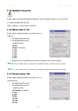
Page 46: ...5 Copyrights 9 6 Power properties 9 7 Battery tab To see main and backup battery level indicators open Start Settings Control panel Battery or double tap on Battery icon in taskbar The option to enab...

Page 47: ...ding to CPU time needed by application Handy Terminal raises the power mode from 104MHz to 624MHz and steps down from 624MHz to 104MHz operating point If you set minimum operation point to 416MHz this...

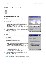
Page 48: ...NT key on the keypad 9 14 Key define Tab 1 Select Start Settings Control Panel Program buttons Key define tab 2 Current key definition file Basic file is set in the windows folder 3 Chose its type Ope...

Page 49: ...tions 10 sec 30 sec by default 1 min 2 min 3 min 4 min 5 min Enable to turn on backlight when a button is pressed or the screen is tapped NOTE To extend battery life it is recommended to set display b...

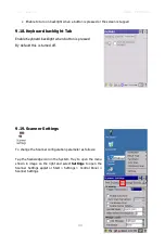
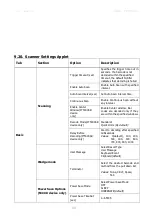
Page 50: ...Keyboard backlight when button is pressed By default this is turned off 9 19 Scanner Settings To change the Scanner configuration parameter as follows Tap the Scanwedge icon in the System Tray to open...

Page 51: ...nter Window IT5300SR device only Enable Center window Bar codes are decoded only if they are within the specified windows Decode Mode IT5300SR device only Standard Quick Omni By default Delay Before D...

Page 52: ...ecifies or enable available detail settings in symbologies Enable this code Tap enable this checkbox to enable the selected bar code type Barcode ID Enter the desired features you wish to transmit as...

Page 53: ...nal provided that the following parameters are met The software program was created for a Windows CE device The terminal has enough memory to store and run the program The program has an EXE CAB or DL...

Page 54: ...ecommend use of Toshiba Tec peripherals power cables and power adapters Use of any non Toshiba Tec peripherals cables or power adapters may cause damage not covered by the warranty 10 5 Communication...

Page 55: ...ontrol Panel PC Connection 10 10 Communicating with the Handy Terminal After setting up both the workstation and the terminal ActiveSync connection should be automatic 1 Connect the Handy Terminal to...

Page 56: ...processor by tapping Start Settings Control Panel System General tab Make a note of the information in the Processor field Generally software for Windows CE devices must be installed to the host works...

Page 57: ...file s and copy them to the Program Files folder on the terminal If you want the program to persist through hard resets save the program to the Autoinstall Cabfile folder AutoInstall Cabfile 3 On the...

Page 58: ...AN On The enable disable state of the radio will survive subsequent soft and hard resets The next step is to configure the connection parameters of the radio to connect to a wireless network Configuri...

Page 59: ...ds for the Bluetooth radio driver to re initialize the radio NOTE Area coverage and Bluetooth radio performance may vary due to environmental conditions or interference caused by other devices microwa...

Page 60: ...es a full charge of the main battery pack in four hours for the standard capacity 2200mAh pack and six hours for the extended capacity 3300mAh pack on the handy terminal The charging time for spare ba...

Page 61: ...th a host device power the terminal and charge the terminal s battery Make sure that the device is securely seated Rubber Feet The bottom panel has four rubber feet to stabilize the unit on a flat sur...

Page 62: ...radle only Using an Ethernet cable you can connect the Single Slot Ethernet cradle to an Ethernet compliant device to facilitate Ethernet communication to and from the terminal This equipment is for i...

Page 63: ...o not short circuit between each contact of the cradle It may cause fire 12 8 Inserting a Terminal 1 Install the battery pack in the terminal 2 Power the base see Powering the Docking cradle Device on...

Page 64: ...gle Slot Docking Cradle HT K10 SE Single Slot Ethernet Cradle Structural Dimensions 135 7mm D x 116 4mm W x 81mm H Weight Single Slot Docking cradle 310g Single Slot Ethernet cradle 320g Material Poly...

Page 65: ...dard Capacity 2200mAh Approx 4 5 hours High Capacity 3300mAh Approx 6 5 hours Max Charging Current 2A Max Standby Current less than 100mA Status LED Green charged Red charging Communication Interface...

Page 66: ...User manual HANDY TERMINAL 65...

Reviews: