- 7 -
2. HARDWARE INSTALLATION
This section describes the functionalities of MC-1600MR / MC-1600MR48 components and guides how to install the device
on the desktop or shelf. Basic knowledge of networking is assumed; please read this chapter completely before continuing
installs the Web Smart Media Converter Chassis.
2.1 Front Panel
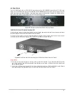
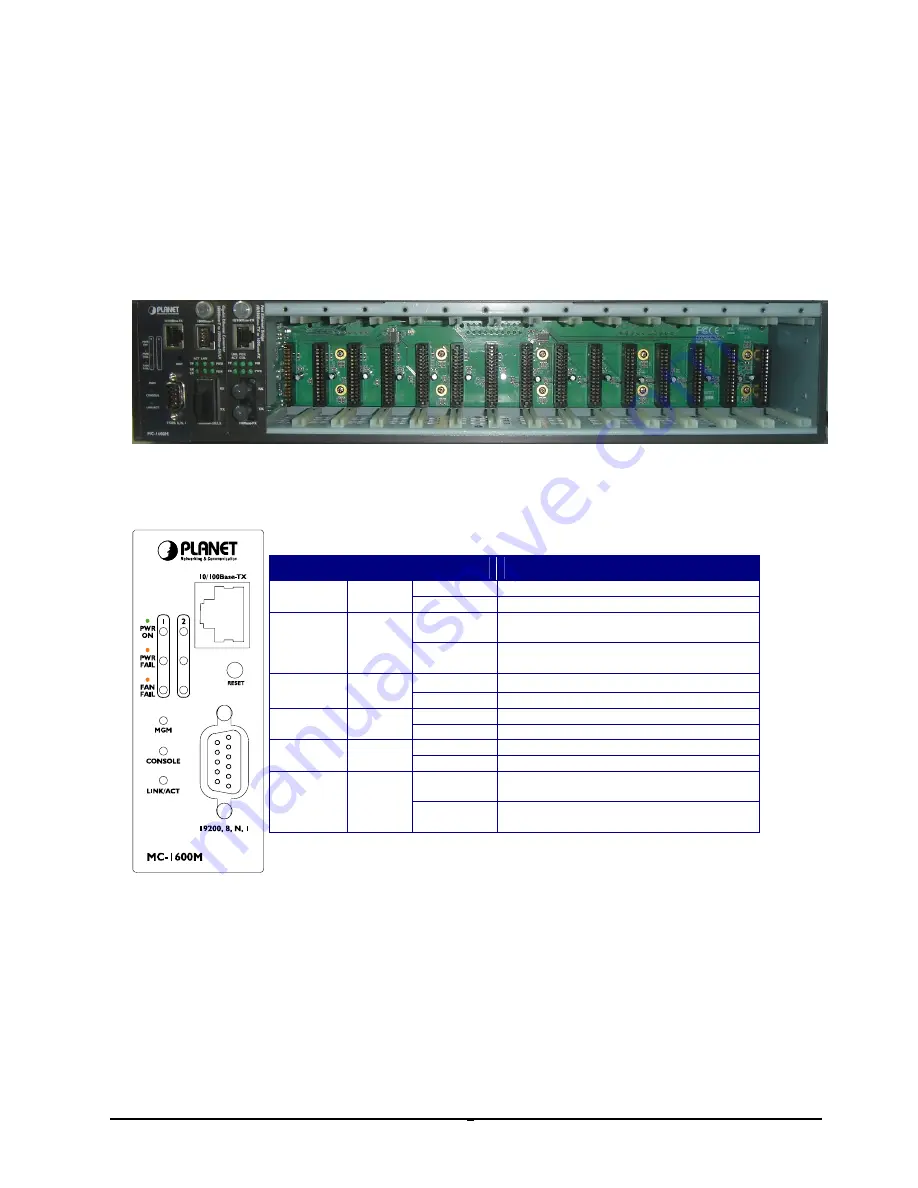
The Web Smart Media Converter Chassis provides one management module and 16-Slots for optional FST-8/ GST-7
series Fast / Gigabit Ethernet Smart Media converter installation.
Figure 2-1:
Web Smart Media Converter Chassis front panel
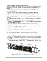
The LED indicators of the management module include power on, power fail, fan fail, MGM, Console and LNK/ACT. The
management module front panel in
Figure 2-2
appears and the LED indicator in
table 2-1
appears.
LED Indicators
LED
Color
LED Status
Function
Lights On
Indicate that the device has power.
PWR ON
Green
Lights Off
Indicate that the device not receive power.
Lights On
Indicate that power is inserted and failed to
work.
PWR FAIL
Amber
Lights Off
Indicate that power is inserted and work
normal.
Lights On
Indicate that fan is failed to work.
FAN FAIL
Amber
Lights Off
Indicate that fan is work normally.
Light blink
Indicate that CPU is working.
MGM
Green
Light Off
Indicate that CPU is not working.
Light blink
Indicate that console port is working.
CONSOLE
Green
Light Off
Indicate that console port is not working.
Light On
The link through that port is successfully
established.
LNK/ACT
Green
Light Off
The link through that port is not established
or run at 10Mbps half / full duplex mode.
Table 2-1:
LED Indicators from Management module front panel
Figure 2-2:
Management module front panel
#
Notice:
Press the RESET button for 5 seconds, the Web Smart Media Converter Chassis will back to factory default mode; the
entire configuration will be erased.


