background image


- 13 - 

3.  WEB SMART MEDIA CONVERTER CHASSIS MANAGEMENT 

This chapter describes how to manage the Web Smart Media Converter Chassis. Topics include: 

- Overview  

- Management methods  

- Assigning an IP address to the Web Smart Media Converter Chassis  

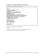
- Logging on to the Web Smart Media Converter Chassis  
 

3.1 Overview 

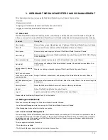
The Web Smart Media Converter Chassis provides a user-friendly, command line under console interface. Using this in-
terface, you can perform various Web Smart Media Converter Chassis configuration and management activities, including: 

Command 

Description 

Show system 

Show software version, Mac address and IP address of Web Smart Media Converter Chassis.

Show IP 

Show current IP subnet address of Web Smart Media Converter Chassis. 

Show power 

Show current power supply unit status of Web Smart Media Converter Chassis. 

Show slot [n] 

Show current per slot status of Web Smart Media Converter Chassis with FST-8 / GST-7 Media 

Converter boards. 

Show redundant [n] 

Show per redundant group status of Web Smart Media Converter Chassis. 

Set slot [n] 

Configure per slot setting of Web Smart Media Converter Chassis with various Media Con-

verter boards. 

Set redundant [n] disable / 

enable 

Disable or enable per redundant group of Web Smart Media Converter Chassis. 

Set IP xxx.xxx.xxx.xxx, 

mmm. mmm, mmm, mmm, 

ggg.ggg.ggg.ggg 

Assign IP address, subnet mask, and gateway of Web Smart Media Converter Chassis. 

Set Pass [oldpass] [ new-

pass] 

Change the default password of Web Smart Media Converter Chassis, the maximum length is 

8 characters. 

Factory Default 

Reset the Web Smart Media Converter Chassis to factory default mode. 

Reboot 

Reboot the Web Smart Media Converter Chassis. 

Logout 

Logout console interface of Web Smart Media Converter Chassis. 

Please refer to the following Chapter 4 and 5 for the details. 

3.2 Management Methods 

There are two ways to manage the Web Smart Media Converter Chassis: 

- Local Console Management via the serial port of Web Smart Media Converter Chassis. 

- Web Management via a network or dial-up connection. 

3.2.1 Local Console Management 

You can manage the Web Smart Media Converter Chassis locally by connecting a VT100 terminal, or a personal computer 
or workstation with terminal emulation software, to the serial port of Web Smart Media Converter Chassis. The terminal or 
workstation connects to the serial port of Web Smart Media Converter Chassis. using a null modem cable that has the 
appropriate connectors on each end. 

This management method is ideal when: 

- The network is unreliable. 

- The Network Manager does not have direct network connection. 


Summary of Contents for MC-1600MR

Page 1: ...User s Manual MC 1600MR MC 1600MR48 16 Slot Web Smart Media Converter Chassis 1...

Page 2: ...preciate your comments and suggestions FCC Warning This equipment has been tested and found to comply with the limits for a Class A digital device pursuant to Part 15 of the FCC Rules These limits are...

Page 3: ...OLE INTERFACE 16 4 1 CONNECT TO PC 16 4 2 LOGIN IN 17 4 3 MAIN MENU SCREEN 17 4 4 GETTING STARTED 18 4 4 1 General Guidelines 18 4 4 2 Show command 19 4 4 3 Set command 23 4 4 4 Factory default 27 4 4...

Page 4: ...Manual is structured as followings Section 2 Hardware Installation It explains the functions of Web Smart Media Converter Chassis and how to install the Web Smart Media Converter Chassis Section 3 Web...

Page 5: ...t slot for option redundant power supply installation A redundant power supply is also provided to enhance the reliability with op tions of either 100 240V AC power supply unit or DC 48V power supply...

Page 6: ...6 Watts 327 BTU Full loading Operate environment 0 50 Degree C 5 90 RH Storage environment 20 70 Degree C 5 90 RH Emission FCC Class A CE mark Management Interface Standards IEEE 802 3 10Base T Ethern...

Page 7: ...ion Lights On Indicate that the device has power PWR ON Green Lights Off Indicate that the device not receive power Lights On Indicate that power is inserted and failed to work PWR FAIL Amber Lights O...

Page 8: ...lide in the power supply unit to the Web Smart Media Converter Chassis To remove a power supply unit out the Web Smart Media Converter Chassis please loose the hand screw counter clockwise and pull ou...

Page 9: ...to the 10 100 RJ 45 port on the management module front panel of the Web Smart Media Converter Chassis B Start to manage the Web Smart Media Converter Chassis through the Microsoft Internet Explorer a...

Page 10: ...nd bracket to the opposite side Step 5 After the brackets are attached to the Web Smart Media Converter Chassis use suitable screws to securely attach the brackets to the rack as shown in Figure 2 6 F...

Page 11: ...mpty expansion slot on the front of the chassis The FST 80x GST 70x Media Converter board can be installed in any expansion slot Step 3 Slide the FST 80x GST 70x Media Converter board into the expansi...

Page 12: ...rk applications It is very flexible for FST 8 GST 7 series to install into the central Web Smart Media converter chassis for centralized management Once the FST 8 GST 7 series of Fast Gigabit Ethernet...

Page 13: ...ble or enable per redundant group of Web Smart Media Converter Chassis Set IP xxx xxx xxx xxx mmm mmm mmm mmm ggg ggg ggg ggg Assign IP address subnet mask and gateway of Web Smart Media Converter Cha...

Page 14: ...te host 3 3 Assigning an IP Address to the Web Smart Media Converter Chassis To manage the Web Smart Media Converter Chassis remotely through the web browser with a Management Station you must assign...

Page 15: ...t for the first time a sign on string appears and you are prompted for a console login user name and password The factory default login username and password is admin Notice 1 For security reason plea...

Page 16: ...Media Converter Chassis Plug the other side of this cable to your PC Hyper Terminal In Windows 98 2000 ME XP launch HyperTerminal create a new connection and adjust settings as below Emulation VT 100...

Page 17: ...admin You may change the password by use set pass command Please always enter the correct user name and password See Figure 4 2 Figure 4 2 Web Smart Media Converter Chassis login screen 4 3 Main Menu...

Page 18: ...with FST 8 GST 7 Media Converter boards Show redundant n Show per redundant group status of Web Smart Media Converter Chassis Set slot n Configure per slot setting of Web Smart Media Converter Chassi...

Page 19: ...in Figure 4 5 appears Figure 4 5 Show command list screen This show command list contains five items Show system Please refer to chapter 4 4 2 1 Show IP Please refer to chapter 4 4 2 2 Show power Plea...

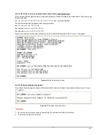
Page 20: ...system command screen 4 4 2 2 Show IP Display the current IP address Netmask and Gateway of Web Smart Media Converter Chassis the IP subnet address information screen in Figure 4 7 appears Figure 4 7...

Page 21: ...nverter Chassis with FST 8 GST 7 Media Converter boards the per slot information screen in Figure 4 9 4 10 appears Figure 4 9 Show slot command screen Figure 4 10 Show slot command n screen Notice dif...

Page 22: ...n Display per redundant group status of Web Smart Media Converter Chassis the per redundant group status screen in Figure 4 11 4 12 appears Figure 4 11 Show redundant command screen Figure 4 12 Show...

Page 23: ...pears Figure 4 13 Set command list screen This set command list contains four items Set slot n Please refer to chapter 4 4 3 1 Set redundant n disable enable Please refer to chapter 4 4 3 2 Set ip xxx...

Page 24: ...at Auto negotiation or Forced Mode TP Speed To set the UTP port runs at 100Mbps or 10Mbps TP Duplex To set the UTP port runs at Full duplex or Half duplex mode TP FC To set the Flow Control of the UTP...

Page 25: ...the ports with even number will be Slave Group Master Slave 1 1 2 2 3 4 3 5 6 4 7 8 5 9 10 6 11 12 7 13 14 8 15 16 Once enable the redundant backup setting function only the Master fiber interface wi...

Page 26: ...68 0 100 The netmask sets to 255 255 255 0 The gateway sets to 192 168 0 254 Means the IP address was changed successfully the IP subnet address setting screen in Figure 4 16 appears Figure 4 16 Set I...

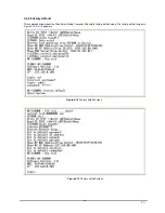
Page 27: ...efault This command allows reset the Web Smart Media Converter Chassis to factory default mode The factory default screen in Figure 4 18 4 19 appears Figure 4 18 Factory default screen Figure 4 19 Fac...

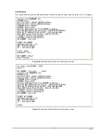
Page 28: ...mmand allows reboot the Web Smart Media Converter Chassis the reboot screen in Figure 4 20 4 21 appears Figure 4 20 Web Smart Media Converter Chassis reboot screen Figure 4 21 Web Smart Media Converte...

Page 29: ...29 4 4 6 Logout This command provides logout the Web Smart Media Converter Chassis the screen in Figure 4 22 appears Figure 4 22 Web Smart Media Converter Chassis Logout screen...

Page 30: ...then use the default IP address 192 168 0 100 to remote configure Web Smart Media Converter Chassis through the Web interface 5 1 Login in to the Web Smart Media Converter Chassis To access the Web b...

Page 31: ...creen of Web Smart Media Converter Chassis 5 2 Chassis Status This section provides current status of power supply unit from Web Smart Media Converter Chassis the screen in Figure 5 3 appears Figure 5...

Page 32: ...en in Figure 5 4 appears Figure 5 4 Converter Status Web Page screen Different parameters provide on FST 8 GST 7 Media Converter boards installation the screen in Figure 5 5 Figure 5 6 appears and tab...

Page 33: ...the LLR function of the Fiber port Fiber Duplex To set the Duplex Mode of Fiber port to Full duplex or Half duplex mode Table 5 1 Descriptions of the FST 80x slot Configuration screen Objects Notice...

Page 34: ...nput new IP address of Web Smart Media Converter Chassis Subnet Mask Allow to input new Subnet Mask address of Web Smart Media Converter Chassis Default Gateway Allow to input new default Gateway of W...

Page 35: ...to take effect The Web Smart Media Converter Chassis will proceed following procedure and ask re login with new IP address The screen in Figure 5 8 5 9 5 10 5 11 appears Figure 5 8 System Configuratio...

Page 36: ...36 Figure 5 10 System Configuration Web Page screen Figure 5 11 System Configuration Web Page screen...

Page 37: ...ation description on each slot of Web Smart Media Converter Chassis the screen in Figure 5 12 appears Figure 5 12 Location Setting Web Page screen After setup completed press Save button to save curre...

Page 38: ...Slave Once enable the redundant backup setting function only the Master fiber interface will work as a major fiber connection and the Slave fiber interface as a backup fiber connection When the system...

Page 39: ...Smart Media Converter Chassis the screen in Figure 5 14 appears Figure 5 14 Password Setting Web Page screen Please input the current password in Old Password space then input new password twice in s...

Page 40: ...following screen in Figure 5 16 appears Figure 5 16 Password Setting Web Page screen Please use the new password to login the Web Smart Media Converter Chassis on next login Notice 1 For security rea...

Page 41: ...r choose this function and the fol lowing screen appears in Figure 5 17 Please press Update button to continue following firmware upgrade process Figure 5 17 Firmware upgrade Web Page screen Please wa...

Page 42: ...Web Smart Media Converter Chassis that deposit in your PC and press Upgrade to start the firmware upgrade process The screen in Figure 5 19 appears Figure 5 19 Firmware upgrade Web Page screen Please...

Page 43: ...Figure 5 21 please press Re Login button to re login web interface of Web Smart Media Converter Chassis with latest firmware version the screen in Figure 5 22 appears Figure 5 21 Firmware upgrade Web...

Page 44: ...mode after choose this function and the following screen appears in Figure 5 23 Please press OK button to take effect and the Web Smart Media Converter will reboot automatically please refresh current...

Page 45: ...unction and the following screen appears in Figure 5 25 Please press OK button to take effect and the Web Smart Media Converter will reboot auto matically please refresh current Web page or create a n...

Page 46: ...a Converter Chassis login Web Page screen 5 11 Logout This section allows to logout the Web Smart Media Converter Chassis the screen in Figure 5 27 5 28 appears Figure 5 27 Web Smart Media Converter C...

Page 47: ...47 Figure 5 28 Web Smart Media Converter Chassis login Web Page screen...

Page 48: ...he LLCF function for troubleshooting a remote connection When LLCF is enabled the FL TP ports do not transmit a link signal until they receive a link signal from the opposite port The diagram below sh...

Page 49: ...a Media Switch Hub Management Station w SNMP Converter Converter w SNMP Station LED lit established link LED unlit no link LLCF is ON LLCF is ON Fiber Cable If one of the optical conductors is bad as...

Page 50: ...s also provide local command line console and remote Web interface for efficient management Can I install FT 70x FT 80x and GT 70x series Media converter into the Web Smart Media Converter Chassis Sol...

Page 51: ...ed 6 Rx receive Tx transmit 7 8 Not used A 2 RJ 45 cable pin assignment The standard RJ 45 receptacle connector There are 8 wires on a standard UTP STP cable and each wire is color coded The following...

Reviews: