background image

4    Clean Pole Installation and User’s Guide (OM720-02)

OPERATOR’S SAFETY SUMMARY

Safety Summary

When using your Clean Pole Power System, basic safety precautions should always be
followed to reduce the risk of fire, electric shock, and injury to persons, including the
following:

Read Instructions

Read and follow all safety and operating instructions.

Use the Proper Power Source

Operate only from the type of power source indicated on the rating label. To disconnect from
the power source, remove the power cord. This product is intended to run from a power
source supplying not more than 120 VAC RMS between the supply conductors, or between
supply conductor and ground. Refer to Service Safety Summary for battery replacement
information.

Grounding

This unit is Class II (double insulated), and is provided with a 3-wire grounding type power
cord.

Power Cord

Use only the power cord and connector that is specified for your product and that is in good
condition. Refer cord and connector changes to qualified service personnel. When the cord is
not in use, remove to avoid damage.

Do Not Operate in Explosive Atmospheres

To avoid explosion, do not operate this product in an explosive atmosphere.

Do Not Remove Covers or Panels

Product covers and panels provide significant protection against electrical shock and heat
sources that may cause burns. Do not operate the product with covers removed.

Dispose of Batteries Safely

Federal law requires that Lead Acid batteries be disposed of in a safe and ecologically sound
fashion. If in doubt as to how to accomplish this please contact your state government or
Planar Systems for assistance.

Ventilation

Avoid overheating by keeping slots and openings unblocked.

Summary of Contents for Clean Pole

Page 1: ...Planar Clean Pole Installation and User s Guide Model Number M4POLE PS The Definition of Quality...

Page 2: ...ms Inc This document is subject to change without notice While every attempt at accuracy is made Planar Systems assumes no responsibility for any errors that may appear in this document Planar provide...

Page 3: ...ms and Symbols 5 ASSEMBLY INSTRUCTIONS 6 Introduction 6 Unpacking and Assembly Instructions 6 Disassembly Process 11 Connecting the Clean Pole Charger 12 Charging a Battery 12 OPERATING INSTRUCTIONS 1...

Page 4: ...iv Clean Pole Installation and User s Guide OM720 02...

Page 5: ...base of the Clean Pole The user may choose either an audible or visual alert when the battery falls below a minimum charge To choose use the toggle switch on the top of the unit With this innovative...

Page 6: ...tion of the warranty period and request a Return Material Authorization Number If the configuration has been modified in any manner the product must be returned to its original configuration before an...

Page 7: ...er person s rendering of technical advice assistance or services in connection with the buyer s order of the goods furnished hereunder The Buyer is not relying on Planar s skill or judgment to select...

Page 8: ...unit is Class II double insulated and is provided with a 3 wire grounding type power cord Power Cord Use only the power cord and connector that is specified for your product and that is in good condi...

Page 9: ...you to possible hazards or other conditions of which you may need to be aware These terms and conditions are shown in the following tables Terms and Symbols in the Manual CAUTION CAUTION statements in...

Page 10: ...instructions apply to both models M4POLE PS FOUR WHEELED CLEAN POLE with Rechargeable Power M4POLE NPS FOUR WHEELED CLEAN POLE with the AC converter brick Unpacking and Assembly Instructions Disassem...

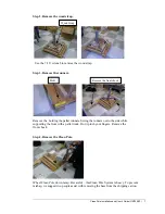
Page 11: ...he front chock Remove the holding the pallet runners Swing the runners out to the side while supporting the front with a pallet truck Don t pinch your fingers Remove the front chock Step 4 Remove the...

Page 12: ...and is secure in the rubber strain relief and cable guide The cable will run up the back of the center column Step 2 Check that cable is plugged in Mount pins Power Connector Mount screws Check to se...

Page 13: ...len wrench Mount the Clean Screen computer mounting bolts mounting bolts Attach the Clean Screen head to the tilting plate on the worksurface with four 10 32 x Phillips pan head screws Adjust the tilt...

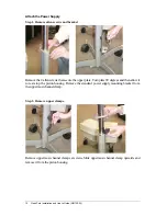
Page 14: ...screws that secure the upper plate Turn plate 90 degrees and then allow it to rest atop the piston housing Remove the standard power supply mounting bracket from the uppermost channel clamp Step 2 Rem...

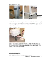
Page 15: ...nsure that the two rubber feet rest securely atop the legs of the cart Adjust the channel clamp if need be and then tighten securely Attach the PS bracket now Step 4 Position power supply Place the PS...

Page 16: ...ging for more than 12 hours and the indicator on the charger control panel is still not registering a full charge the battery may need replacement or refurbishment Please call Planar Systems Customer...

Page 17: ...en working near a wall outlet or during idle times to keep the battery charged and ready for use When using your Clean Pole Power System near a wall outlet you should always keep it plugged in to keep...

Page 18: ...nasty Division UPS12 270 battery or equivalent When selecting batteries consider the flame rating and sealed nature of the original battery Also consider the amount of mechanical abuse the battery mus...

Page 19: ...rminals are placed on the side of the black vertical pole 2 Reinstall the aluminum retaining band over the top of the battery using the 5 16 wrench to replace the 6 kepnut 3 Using the 7 16 wrench reco...

Page 20: ...pan head screws from the top of the battery charger casing 3 Remove the top Be careful not to damage or disconnect the wires connected to the LED Siren switch 4 Using a vacuum and a soft brush remove...

Page 21: ...ing is ignored and the unit is not plugged in for recharge The battery and charger combination allows for an average of 16 hours of use without AC power The Clean Pole will recharge in approximately 1...

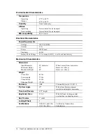
Page 22: ...ll Lead Acid battery Mechanical Characteristics Dimensions Stand Diameter 24 diameter Wheel centers from central axis Minimum Height 25 Home row of keys Maximum Height 44 Home row of keys Weight Clean...

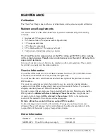
Page 23: ...503 690 6960 between 8 00 AM and 5 00 PM Pacific Time Monday through Friday You will need the unit s serial number and a brief description of the problem to receive a RMA number If a repair is require...

Page 24: ...06 1992 Tel 1 503 690 1100 Fax 1 503 690 1493 sales planar com app_eng planar com Planar Systems Inc Olarinluoma 9 P O Box 46 FIN 02201 Espoo Finland Tel 358 9 42 0010 Fax 358 9 420 0200 intlsales pla...

Reviews: