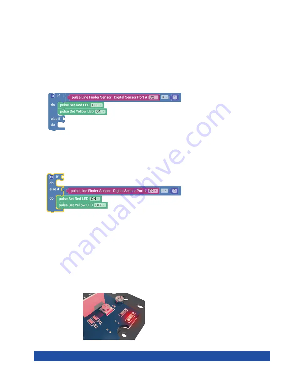
If the if portion of the loop block isn’t true, then the else if portion enables you to
test for a different condition. If this condition is met, then the blocks within the do
section under the else if section will run. In the else if portion, the output of the Line
Finder Sensor must equal 0, or LOW (Figure 40).
The Line Finder Sensor can return a value of “1” (HIGH) or “0” (LOW). A value of “1” is
returned when the Line Finder Sensor detects a dark line or a nonreflective surface;
a value of “0” is returned when the Line Finder Sensor detects a white or reflective
surface.
If the Line Finder Sensor detects a line or a nonreflective surface, then it turns
the red LED on. Think of it as an object placed in its path. The red LED on the Line
Finder Sensor also lights up. In the program, this occurs when the line variable is set
to LOW.
If the Line Finder Sensor detects a white or reflective surface, it turns the yellow LED
on. In the program, this occurs when the line variable is set to HIGH (Figure 41).
Figure 39
Figure 40
Figure 41
Further Investigate
This sketch introduces a program structure, new blocks, and a comparison
statement. The program structure is an “if” statement, the reading of the sensor, and
the comparison statement is “=” (equal to). The comparison statement “=” (equal
to) defines a type of test. In this sketch, the input of the Line Finder Sensor will turn
different LEDs on or off.
The basic “if” statement enables us to test for a certain condition. If this condition is
met, then the program can perform an action. If the variable in the if section of the
loop block is true, then the blocks within the do section are run. In this instance, the
output of the Line Finder Sensor must equal 1, or HIGH, for the do section to run
(Figure 39).
Getting Started Activities
39
Summary of Contents for tetrix prime
Page 1: ...44301 TETRIX PULSE Robotics Controller Programming Guide...
Page 7: ...PULSE Controller Technology Overview Getting Started 5...
Page 61: ...Step 9 Step 10 Step 12 Step 14 Step 11 Step 13 Building and Coding the PULSE CodeeBot 59...
Page 62: ...Step 18 Step 17 Finished Assembly Step 16 Step 15 60 Building and Coding the PULSE CodeeBot...
Page 73: ...Step 1 0 Step 1 1 Build two like this Building and Coding the PULSE CodeeBot 71...
Page 74: ...Step 1 2 Step 1 3 72 Building and Coding the PULSE CodeeBot...
Page 75: ...Step 1 4 Building and Coding the PULSE CodeeBot 73...
Page 78: ...Step 2 2 Step 2 3 76 Building and Coding the PULSE CodeeBot...
Page 79: ...Step 2 4 Step 2 5 Building and Coding the PULSE CodeeBot 77...
Page 80: ...Step 2 6 Step 2 7 78 Building and Coding the PULSE CodeeBot...
Page 81: ...Step 2 8 Building and Coding the PULSE CodeeBot 79...
Page 83: ...Step 3 0 Step 3 1 Building and Coding the PULSE CodeeBot 81...
Page 84: ...Step 3 2 82 Building and Coding the PULSE CodeeBot...
Page 85: ...Step 3 3 Building and Coding the PULSE CodeeBot 83...
Page 87: ...Step 4 0 Step 4 1 Building and Coding the PULSE CodeeBot 85...
Page 88: ...Step 4 2 86 Building and Coding the PULSE CodeeBot...
Page 89: ...Finished assembly should look like this Building and Coding the PULSE CodeeBot 87...
Page 131: ...GS Activity 4 extension GS Activity 5 extension Appendix 129...
Page 144: ...142 Notes...
Page 145: ......


