background image

Manual for StealthTouch M5-M7 with Core Pentium & Core i-Series Model v1.0 


Page 13 


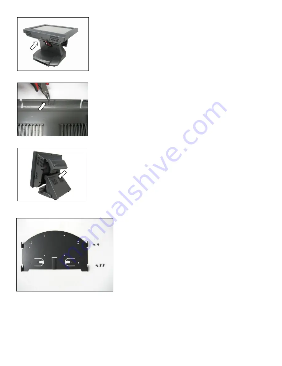
9.   

Cut the cable slot on back cover (see arrow). 


10. 

 Install back cover to the Base. 


2.6 

Installing wall mount/VESA mount (optional, for VESA 75 Pole only) 


Package Overview: 
Wall Mount bracket [#16-M5-101] -----------1 pcs 
2. 3x6, Black screw [10-S3006BB] -------------2 pcs 
3. 4x8, Black screw [#10-S4008SB] -----------3 pcs 


Summary of Contents for StealthTouch M5

Page 1: ...Manual StealthTouch M5 M7 with Core Pentium Core i Series If you need further assistance use one of the following Web http www pioneerposftp com Download VGA Network Audio Touch screen OPOS drivers Ob...

Page 2: ...POS Solutions Inc Trademarks used in this manual PioneerPOS and PioneerPOS Logo are trademarks of Pioneer POS Solutions Inc Microsoft Windows Windows are trademarks of Microsoft Corporation 2014 Pion...

Page 3: ...Using StealthTouch M5 M7 system 15 Chapter 3 Touch screen panel 15 Chapter 4 Network 16 Chapter 5 Serial port RS232 COM ports 18 Section C Using StealthTouch M5 M7 accessories 20 Chapter 6 Using Custo...

Page 4: ...s with built in PC as well as touch monitor with different sizes About this guide This manual is intended to be use as a reference for field service as well as workshop repair It is prepared to our be...

Page 5: ...mulation 24V Compact Flash Reader Optional Speakers 2 Watts Stereo optional Mounting Options Standard Desktop Base Option Wall or VESA mount please call for part Security Lock Bolted 4mm screw or Kens...

Page 6: ...etting started with StealthTouch M5 M7 system Chapter 1 Identifying controls ports and peripherals 1 1 Identifying controls and ports Front View Left View Right View Side USB Slot Card Reader Port Opt...

Page 7: ...FSP1501 Dimension 171mm x 40mm x 72 mm Output DC Cable Length 1 8m Power LED YES blue Power Input AC 100 240V 2A 50 60Hz Power Output DC Power 24V 5 0A Max Power 150W Power Input 24V Power Output E SA...

Page 8: ...Magnetic Card Reader Magnetic card reader Track 1 2 Keyboard Wedge Part Number 46B D21000 MSR Magnetic Card Reader and or Fingerprint Reader Part Number 46B D21F01 Customer Display Integrated Rear Cu...

Page 9: ...ly into a wall outlet Lightning or power surge may damage the system Always connect the power through a surge protector or uninterruptible power supply UPS unit 2 2 Connecting cables to I O panel 1 Ti...

Page 10: ...em 2 3 Connecting network The LAN network port is located on the I O Panel StealthTouch M5 M7 also comes with optional build in wireless LAN 2 4 Installing card reader and or finger print reader optio...

Page 11: ...ews 2 5 Installing customer display rear display optional 1 Tilt terminal and pull the back cover upwards to open 2 Install the rear display to the unit secure it with four M4 x 8mm Big Cap Black P N...

Page 12: ...P N 34 319 122155 to the connector on the Rear Display unit 5 Tilt the unit and remove the I O Panel cover see arrow 6 Route the Rear Display s cable to the front 7 Connect the display s cable to COM...

Page 13: ...ge 13 9 Cut the cable slot on back cover see arrow 10 Install back cover to the Base 2 6 Installing wall mount VESA mount optional for VESA 75 Pole only Package Overview Wall Mount bracket 16 M5 101 1...

Page 14: ...Manual for StealthTouch M5 M7 with Core Pentium Core i Series Model v1 0 Page 14 2 6 1 Wall mount 2 6 2 VESA 75 mount...

Page 15: ...r Windows 7 or Windows 8 OS StealthTouth M5 M7 s Touch Screen can be operated with finger or soft stylus If you have re installed the driver software you need to open TouchKit to re calibrate the touc...

Page 16: ...the network cable and it should work In case you need to check your network setting you can follow the instruction below 1 Start Control Panel System 2 Under Hardware Tab select Device Manager 3 Expan...

Page 17: ...ess card 1 Go to Start Program Intel PROset Wireless 2 Click on Intel PROset Wireless to setup wireless utility 3 You can also access Intel PROSet Wireless Utility by double clicking the Intel PROSet...

Page 18: ...ment for RS232 Serial Port PIN Serial Port Signal Description 1 DCD Data Carrier detect 2 RX Receive data 3 TX Transmit data 4 DTR Data Terminal Ready 5 GND Signal Ground 6 DSR Data Set Ready 7 RTS Re...

Page 19: ...nd COM2_RI on the System Board Please see table below for setting of these two jumpers Power will be available on Pin 1 Warning If COM Port 2 is set with power users shall not plug in other devices to...

Page 20: ...ced Epson CD7220 CD5220 II PD3000 6 2 Reprogram rear display protocol emulation Please obtain the utility to reprogram Rear Display Protocol by contacting PioneerPOS Technical Support If you need to r...

Page 21: ...ta Max 40 Byte for ASCII you may leave the field blank or you can type any sentence you would like for the scroll data 4 When you are ready click Write to EEPROM Y 5 A new pop up window will show up T...

Page 22: ...sassemble the system 2 Protect your own safety with insulating glove 3 Warning To prevent electric shock DO NOT open up Power Supply Unit CRT Monitor Unit 7 3 Protecting your data 1 Make sure that you...

Page 23: ...is not on double check the connection of power chord to the Power Supply Unit 3 Make sure that the power cord is plugged in to the power supply block completely 3 Check if you have the right power ad...

Page 24: ...ey too early To resolve this issue please restart the system and try again c You will see a screen with Windows Advanced Option Menu with dark background after the boot up screen d Please select Safe...

Page 25: ...mple if you are using Western Digital hard drive you may use Data Lifeguard Tools available at Western Digital Support Website Note PioneerPOS uses Western Digital brand WD Blue series for HDD on Stea...

Page 26: ...kit utility screen to add touch adapter 3 Re install Touchkit utility driver TouchKit utility driver can be downloaded from PioneerPOS com 4 Since Touch Panel Controller is controlled by Serial Contro...

Page 27: ...t this problem by removing MSR and then put 2 jumpers to the top 4 pin Please contact PioneeerPOS Technical Support if you have a defective MSR Caution If you put the jumper to the wrong pin it might...

Page 28: ...description Magnetic Stripe Reader MSR cannot read cards 1 Verify the issue by trying to swipe MSR with a different card Sometimes the issue may be caused by a defective card 2 Open notepad program a...

Page 29: ...ch M5 M7 with Core Pentium Core i Series Model v1 0 Page 29 9 3 Bar Code Reader issue Problem Description Barcode reader not working 1 Make sure that keyboard terminator is connector to PS 2 connector...

Page 30: ...Manual for StealthTouch M5 M7 with Core Pentium Core i Series Model v1 0 Page 30 Section E System Board description Chapter 10 System Board Layout...

Page 31: ...nector HEADER 1X3P S T 2 0mm DIP Jumper MINI JUMPER 2P 2 0MM F SMT 1 2 5V 2 3 3V default J2 INVERTER voltage SEL Connector HEADER 1X3P S T 2 0mm DIP Jumper MINI JUMPER 2P 2 0MM F SMT 1 2 12V default 2...

Page 32: ...her devices due to user modification Call 909 468 9757 or email support pioneerpos com for help COM2_ RI COM2 RI Jump setting Connector HEADER 2X4P S T 2 0mm DIP Jumper MINI JUMPER 2P 2 0MM F SMT 1 2...

Page 33: ...Open Open Close 800x480_18bit_60Hz Open Open Close Open 800x600_18bit_60Hz Open Open Close Close 1024x600_18bit_60Hz Open Close Open Open 1024x768_18bit_60Hz Open Close Open Close 1024x768_24bit_60Hz...

Reviews: