Other connections
10
85
En
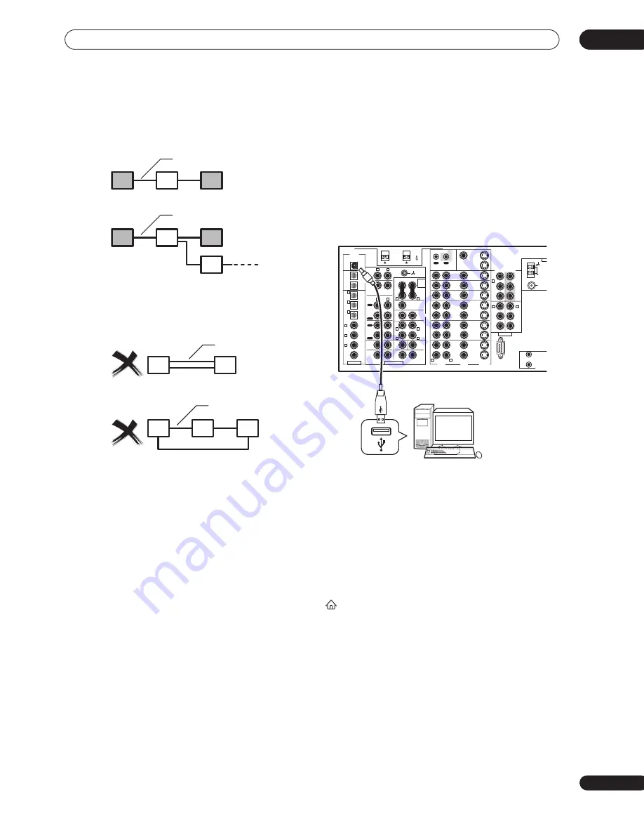
When setting up an i.LINK network, it’s important that
the components form an open ended chain (fig. 1), or a
tree (fig. 2).
The system will not work if the connected components
form a loop. If a loop is detected, the message
LOOP
CONNECT
shows in the display. Figs. 3 and 4 show
connections that form a loop.
Another consideration when connecting i.LINK devices
is the speed of the interface. At present there are three
speeds; S100 (slowest), S200 and S400 (fastest). This
receiver uses the S400 type. Although you can use
components with different speeds together, we
recommend connecting slower-speed components at
the edge of the network if possible (shown by the shaded
boxes in figs. 1 and 2). This will keep the network free of
bottlenecks.
When used within an i.LINK network, this receiver must
be on for the i.LINK connection to be maintained. Other
components in the network may or may not maintain the
connection in standby (none will when the power is
completely off)—check the operating instructions
supplied with individual components. Note that the audio
may be momentarily interrupted if a component in the
i.LINK network is switched on/off, or its i.LINK
connection is switched on/off.
This product complies with the following i.LINK interface
specifications:
1) IEEE Std. 1394a-2000, Standard for a High Performance
Serial Bus
2) Audio and Music Data Transmission Protocol 2.0
Following the standard for AM824 sequence adaptation
layers, the product is compatible with IEC60958 bitstream,
DVD-A and SACD.
Using the USB interface
It is possible to listen to multichannel audio sources from
your computer by connecting to the USB interface on the
rear of this receiver. Depending on your model of
computer and the software installed, you can listen to
any source compatible with your operating system
through the speaker setup you’ve connected to this
receiver.
1
Connect your computer’s USB terminal to the
USB terminal on the rear panel of this receiver.
2
Switch on your computer and this receiver.
3
If you’re connecting for the first time, wait for
the USB driver installation to finish.
The installation may take a minute or two to complete.
Make sure you leave the USB cable connected until the
dialog box indicates that the USB setup is finished. Note
that some older operating systems may require a disc for
installation.
4
Press ‘USB’ on the remote control Home menu
(
) screen.
You can also use the
INPUT SELECTOR
dial on the front
panel to select
USB
.
5
Make any necessary settings required to select
the USB interface as your computer audio output.
You will need to access your speaker settings from the
Control Panel
of your operating system:
•
Windows
®
XP
– Select
Sound, Speech, and Audio
Devices
, and then select
Change the speaker
settings
. Select
Audio
, then
PIONEER AV Receiver/
Amplifier
from the drop down menu.
fig. 1
fig. 2
i.LINK cable
i.LINK cable
fig. 3
fig. 4
i.LINK cable
i.LINK cable
PLAY
PLAY
AUDIO
POWER
AMP
IN
PRE OUT
AUDIO
PHONO
FRONT
SUB W
CENTER
SUR-
ROUND
BACK
SUR-
ROUND
SUB W.
CENTER
SUR-
ROUND
CD-R/
TAPE1/
MD
TAPE 2
MONITOR
CD
IN
IN
IN
OUT
IN
OUT
VIDEO
AUDIO
S2 VIDEO
USB AUDIO
S400
(AUDIO)
OUT 2
OUT 1
(CD-R/
TAPE1/
MD)
(DVR/
VCR1)
(SAT)
IN
(CD)
(TV/
DVD)
(DVD/
LD)
(DVD/
LD)
IN
DVR/
VCR1
OUT
DVD/
LD
IN
(DVD/
LD)
IN
Y
P
B
P
R
P
B
P
R
2
RF
IN
IN
IN
Y
P
B
P
R
Y
P
B
P
R
Y
TV/
DVD
IN
SAT
IN
IN
IN
IN
IN
OUT
OUT
OUT
1
2
12V TRIGGER
DC OUT 12V
TOTAL 100mA M
IN
IN
IN
VCR2
OUT
IN
VCR3
OUT
IN
1 IN
REC
REC
OUT
DIGITAL
MONITOR
OUT 1
MONITOR
OUT 2
MONITOR
OUT
COMPONENT VIDEO
ASSIGNABLE
MULTI CH INPUT
RS-232C
ANTE
AM LOOP
ANTENNA
FM
75
Ω
UNB
2 IN
3 IN
4
IN
5
R
L
R
L
R
L
R
L
(Single)
1
(Single)
2
(Single)
R
L
R
L
R
L
R
L
R
L
IN
6
ASSIGNABLE
CONTROL
IN
3
1
2
VSX-AX10Ai
Personal computer


