138
PDP-433CMX
1
2
3
4
C
D
F
A
B
E
1
2
3
4
1
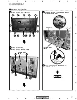
Remove the rear case (M). (Screws
×
20)
3
Remove the terminal panel CMX. (Connector, screws
×
9)
4
Remove the screw of earth block on the I/O Assy.
5
Remove the RGB base. (Screws
×
4)
7
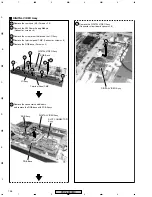
Remove the DIGITAL VIDEO Assy.
(Connector, circuit board spacers
×
6)
6
Remove the connectors and binders,
and remove the RGB base with PCB Assys.
2
Remove the SW Power Supply Module.
(Connector, screws
×
4)
DIGITAL VIDEO Assy
4
5
5
5
5
×
2
×
2
×
2
×
2
4
6
7
4
4
3
4
Terminal Panel CMX
RGB Base
DIGITAL VIDEO Assy
I/O Assy
RGB Base
SLOT CONNECTOR
Assy
DIGITAL VIDEO Assy
RGB Assy
DIGITAL VIDEO Assy
Summary of Contents for PDP 433CMX
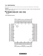
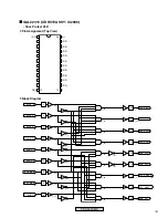
Page 165: ...165 PDP 433CMX Pin Assignment Top View CXA3516R RGB ASSY IC4603 AD PLL IC ...
Page 166: ...166 PDP 433CMX Block Diagram ...
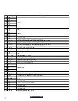
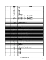
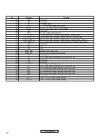
Page 167: ...167 PDP 433CMX Pin Function ...
Page 168: ...168 PDP 433CMX ...
Page 169: ...169 PDP 433CMX ...

