108
PDP-433CMX
1
2
3
4
C
D
F
A
B
E
1
2
3
4
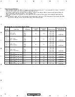
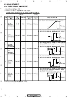
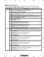
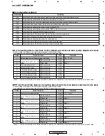
Input Signal Step
Adjusting Method
Video signal
RGB (PC)
signal
14
Increase the MAT CONT adjustment value of OFFSET-RGB1 by 3.
OFFSET mode: Select RGB 1 mode with the top and bottom keys.
MAT CONT : "1" key
Increase the adjustment value by 3 with the right and left keys.
15
Increase the MAT BRIGHT adjustment value of OFFSET-RGB1 by 2.
OFFSET mode: Select RGB 1 mode with the top and bottom keys.
MAT BRIGHT : "2" key
Increase the adjustment value by 2 with the right and left keys.
16
Turn the ACL SW setting to ON.
INITIALIZE mode
ACL SW : "3" key
Select ON with the right and left keys.
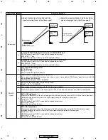
Black level of
the Green signal
Green signal
waveform
Adjust the black level of the Red and Blue
signals referring to that of the Green signal
Black level of
the Red or Blue signal
Signal amplitude
of the Green signal
Green signal
waveform
Red or Blue
signal
waveform
Red or Blue
signal
waveform
Adjust the signal amplitude of the Red and Blue
signals referring to that of the Green signal
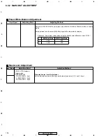
1
Input a RGB (PC) signal to the INPUT1 or INPUT2.
Use a signal consisting of the luminance signal only, such as a ramp signal or STEP signal, whose black level (0IRE)
and gradation can be checked.
• Recommended signal: VESA VGA@60Hz
2
Set the unit to Standby mode then to Factory mode.
MENU
→
SET
→
POWER ON
3
Take a trigger of the oscilloscope with HD_PLL (3.3Vp-p) of K4805.
4
Measure the signal waveform of the Green signal at K4603, and measure the black level (0IRE) and amplitude.
5
AD R LOW adjustment
Measure the black level (0IRE) of the Red signal at K4602, and adjust the level of AD R LOW so that its black level
(0IRE) becomes the same as that of the Green signal measured in step 9 of video signal.
Tolerance:
±
0.05V
OFFSET mode: Select RGB 1 mode with the top and bottom keys.
AD R LOW : "9" key
Adjust with the right and left keys.
6
AD R HIGH adjustment
Measure the signal amplitude of the Red signal at K4602, and adjust the level of AD R HIGH so that its signal
amplitude becomes the same as that of the Green signal measured in step 9 of video signal.
Tolerance:
±
0.05V
OFFSET mode: Select RGB 1 mode with the top and bottom keys.
AD R HIGH : "6" key
Adjust with the right and left keys.
Summary of Contents for PDP 433CMX
Page 165: ...165 PDP 433CMX Pin Assignment Top View CXA3516R RGB ASSY IC4603 AD PLL IC ...
Page 166: ...166 PDP 433CMX Block Diagram ...
Page 167: ...167 PDP 433CMX Pin Function ...
Page 168: ...168 PDP 433CMX ...
Page 169: ...169 PDP 433CMX ...


