103
PDP-433CMX
5
6
7
8
5
6
7
8
C
D
F
A
B
E
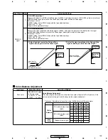
6.2 ADJUSTMENT REQUIRED WHEN THE SET IS REPARED OR REPLACED
Fig. 1 Configuration of the PC Board (rear side view)
RGB Assy
When repaired
When replaced
White balance adjustment
DIGITAL VIDEO Assy
When repaired
No adjustment required.
When replaced
SW POWER SUPPLY Module
When replaced
No adjustment required.
1. Adjustment is unnecessary when only the DIGITAL VIDEO
Assy is replaced.
2. When the RGB Assy is replaced at the same time as this
assembly, remove the IC1204 (24LC04(1)SN-TBB) from the
old PC board of the DIGITAL VIDEO Assy and attach it to
the new PC board.
3. If you are reusing the collected old PC board as a service
part, attach the new IC1204 to the board.
1. Adjustment is impossible when the Matrix IC or
AD/PLL/AMP IC is replaced.
2. Adjustment is unnecessary in other cases.
Y DRIVE Assy
When replaced
1. Panel white balance adjustment
X DRIVE Assy
When replaced
1. Panel white balance adjustment
Video Card (PDA-5002)
When repaired
When replaced
No adjustment required.
1. Y LEVEL adjustment
2. Color difference and TINT adjustment
DIGITAL VIDEO
Assy
X DRIVE
Assy
Video Card
(PDA-5002)
Y DRIVE
Assy
RGB Assy
SW POWER SUPPLY
Module
Summary of Contents for PDP 433CMX
Page 165: ...165 PDP 433CMX Pin Assignment Top View CXA3516R RGB ASSY IC4603 AD PLL IC ...
Page 166: ...166 PDP 433CMX Block Diagram ...
Page 167: ...167 PDP 433CMX Pin Function ...
Page 168: ...168 PDP 433CMX ...
Page 169: ...169 PDP 433CMX ...


