GEX-P10XMT/XN/UC
57
5
6
7
8
5
6
7
8
C
D
F
A
B
E
-
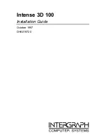
Pin Functions(PEG100A)
Pin No.
Pin Name
I/O
Function and Operation
1-5
NC
Not used
6
BYTE
I
External bus width select input
7
CNVSS
I
Processor mode select input
8,9
NC
Not used
10
reset
I
Reset input
11
XOUT
Crystal oscillator connection pin
12
VSS
GND
13
XIN
Crystal oscillator connection pin
14
VCC
Power supply (3.3V)
15
NMI
Not used
16
NC
Not used
17
STBY
I
Stand-by sense input
18
DATAINT
I
LSDP receive interrupt input
19-26
NC
Not used
27
NAVIRX
I
Navigation system I/F input
28
NAVITX
O
Navigation system I/F output
29
NC
Not used
30
LSDPRX
I
LSDP signal input
31,32
NC
Not used
33
MAINTX
O
Main microcomputer I/F output
34
MAINRX
I
Main microcomputer I/F input
35-38
NC
Not used
39
EPM
Not used
40
NC
Not used
41
TESTIN
I
Test program sense input
42-59
NC
Not used
60
VDD
Power supply (3.3V)
61
NC
Not used
62
VSS
GND
63-69
NC
Not used
70
FLASHIN
Not used
71-75
NC
Not used
76
RDT
I/O
EEPROM data input/output
77
RCK
O
EEPROM clock output
78
RCS
O
EEPROM chip enable output
79-93
NC
Not used
94
AVSS
Analog GND
95
NC
Not used
96
VREF
Analog reference voltage
97
AVCC
Analog power supply
98-100
NC
Not used
* PEG100A
25
26
50
51
75
76
100
1
Summary of Contents for GEX-P10XMT - Satellite Radio Tuner
Page 14: ...GEX P10XMT XN UC 14 1 2 3 4 1 2 3 4 C D F A B E A a A b A a A b 1 2 A a 1 2 1 ...
Page 15: ...GEX P10XMT XN UC 15 5 6 7 8 5 6 7 8 C D F A B E A a A b A a A b 1 2 A a 1 2 2 B CN502 ...
Page 17: ...GEX P10XMT XN UC 17 5 6 7 8 5 6 7 8 C D F A B E A a A b A b 1 2 2 LPF ...
Page 24: ...GEX P10XMT XN UC 24 1 2 3 4 1 2 3 4 C D F A B E 3 4 TUNER UNIT B RF XM ANTENNA ...
Page 25: ...GEX P10XMT XN UC 25 5 6 7 8 5 6 7 8 C D F A B E B 1 2 A CN301 B TUNER UNIT CLK BUFFER ...