


17
enlarge or reduce and the scale message at the lower-left corner of
the screen will also change as the scale changes. Press down the
knob to quickly switch the vertical scale adjustment modes between
“Coarse” and “Fine”.
○
15
Channel Input Terminal.
○
16
Menu Select keys.
○
17
Print Key:
: Press the button to enable the reference waveform
function. By recalling the previously saved waveform, we could
compare it with the current waveform to decide circuit failures.
○
18
USB Host Interface.
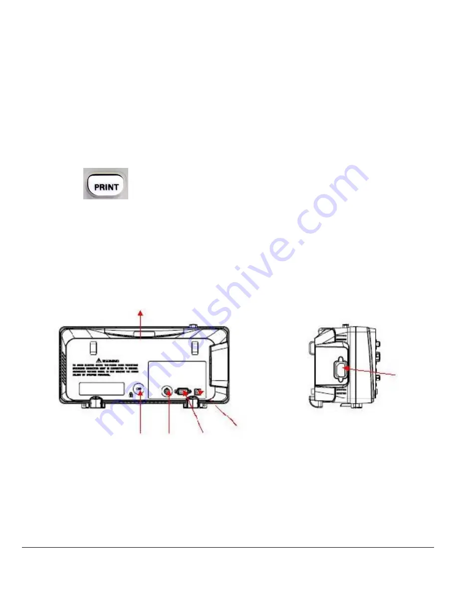
Rear Panel Description
○
1
Handle:
Pull up the handle vertically for easy carrying. Press it down if you
do not need the handle.
○
2
AC Power Input Terminal:
○
1
○
6
○
5
○
4
○
3
○
2


