- 4 -
• Eingangskreis:
- Einkanalig:
Öffnerkontakt von Auslöseelement
zwischen Plusklemme (L+) der Versor-
gungsspannung und Klemme A1
anschließen, S11-S12 und S21-S22
brücken
- Zweikanalig: Öffnerkontakt von
Auslöseelement an S11-S12 und S21-
S22 anschließen
• Rückführkreis:
Externe Schütze in Reihe zu Startkreis
S33-S34 anschließen
Die Sicherheitskontakte sind aktiviert (ge-
schlossen). Die Statusanzeigen für "CH.1",
"CH.2" leuchten. Das Gerät ist betriebs-
bereit.
Wird der Eingangskreis geöffnet, öffnen die
Sicherheitskontakte 13-14/23-24. Die
Statusanzeige erlischt.
Wieder aktivieren
• Eingangskreis schließen.
• Bei manuellem Start zusätzlich Taster
zwischen S33 und S34 betätigen.
Die Statusanzeigen leuchten wieder, die
Sicherheitskontakte sind geschlossen.
Anwendung
In Fig. 2 ... Fig. 6 sind Anschlussbeispiele
für Not-Halt-Beschaltung mit automatischem
und manuellem Start, Schutztüransteue-
rungen sowie Kontaktvervielfachung durch
externe Schütze.
• Circuits d’entrée:
- Commande par 1 canal : câblage du
contact à ouverture entre le potentiel
(L+) de la tension d'alimentation et la
borne A1 (+), pontage entre S11-S12 et
S21-S22
- Commande par 2 canaux: câblage des
contacts à ouverture entre S11-S12 et
S21-S22
• Boucle de retour:
Câblage en série des contacts externes
dans le circuit de rèarmement S33-S34
Les contacts de sécurité se ferment. Les
LEDs "CH.1" et "CH.2" sont allumées.
L’appareil est prêt à fonctionner.
Si le circuit d’entrée est ouvert, les contacts
de sécurité retombent. Les LEDs
s’éteignent.
Remise en route :
• fermer le circuit d’entrée
• en cas de réarmement manuel, appuyer
sur le poussoir de validation entre S33-
S34.
Les LEDs sont à nouveau allumées. Les
contacts de sécurité sont fermées.
Utilisation
Dans les figures 2 à 6 sont représentés les
différents cablages possibles du PNOZ X2/
X2.1 : poussoirs AU avec réarmement
automatique et surveillance du circuit de
réarmement, interrupteur de position et
augmentation du nombre des contacts par
contacteurs externes.
• Input circuit:
- Single-channel: Connect N/C contact
from safety switch between the positive
terminal (L+) of the operating voltage
and terminal A1, link S11-S12 and S21-
S22.
- Two-channel: Connect N/C contact
from safety switch (e.g. Emergency-
Stop) to S11-S12 and S21-S22.
• Feedback control loop:
Connect external contactors/relays in
series with reset circuit S33-S34.
The safety contacts are activated (closed).
The status indicators "CH.1" and "CH.2" are
illuminated. The unit is ready for operation. If
the input circuit is opened, the safety
contacts 13-14/23-24 open. The status
indicator goes out.
Reactivation
• Close the input circuit.
• For manual reset press the button
between S33-S34.
The status indicators illuminate once more,
the safety contacts are closed.
Application
In Fig.2...Fig.6 are connection examples for
Emergency Stop wiring with automatic and
manual reset. Safety gate control as well as
contact expansion via external contactors.
S11
S12
S34
S22
S33
S21
S1
S3
S11
S12
S34
S22
S33
S21
S1
Fig. 3: nur bei PNOZ X2.1: automat. Start/
Only PNOZ X2.1: automatic reset/
PNOZ X2.1 uniquement: réarmement
automatique
S34
S33
S11
S22
S12
S21
S1
S3
S1
S2
14
K4
K5
13
S33
S34
K4
K5
1L1
1L2
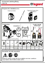
Fig. 6: Anschlussbeispiel für externe
Schütze, einkanalig/Connection example for
external contactors/relays, single-channel/
Branchement contacteurs externes,
commande par 1 canal
S11
S12
S34
S22
S33
S21
UB
(L+)
A1
S1
S3
Fig. 4: Schutztürsteuerung zweikanalig,
manueller Start/Dual-channel safety gate
control, manual reset/Surveillance de
protecteur, commande par 2 canaux
Fig. 2: Eingangskreis zweikanalig, manueller
Start/Two-channel input circuit, manual
reset/Commande par 2 canaux, réarmement
manuel
Fig. 5: Eingangskreis einkanalig, manueller
Start/Single-channel input circuit, manual
reset/Commande par 1 canal, réarmement
manuel
S1/S2: Not-Halt- bzw. Schutztürschalter/
Emergency Stop Button, Safety
Gate Limit Switch/Poussoir AU,
détecteurs de position
S3:
Starttaster/Reset button/Poussoir
de réarmement
betätigtes Element/Switch
activated/élément actionné
Tür nicht geschlossen/Gate
open/porte ouverte
Tür geschlossen/Gate closed/
porte fermée