8
MT 237 – EN ed.2015 (Rev.A)
2.2
CONNECTING THE EQUIPMENT
The valve has to be installed on the line with the arrow on the body positioned in the gas flow direction.
The connections between the equipment and the piping have to be carried out using a stainless steel or copper pipe, having a minimum
internal diameter of 8 mm.
To obtain the correct operation, it is essential that the downstream sensing line is connected to a straight section of the piping itself,
having a length equal to 4 times the piping diameter (therefore, without any possible signal turbulence), as well as that the maximum gas
speed at the sensing point does not exceed 30 m/sec.
In order to prevent impurities and condensation to deposit in the pressure sensing tubes, it is advisable to provide for the following:
the tubes shall always be positioned on a descending slope towards the connection of the outlet piping with a slope of about 5 -
10%;
tube branch connections shall always be welded on the upper part of the piping itself and the hole on the piping shall not show
any burrs or projections towards the internal side.
To avoid breakages or unwanted deformations, it is recommended to provide for the following:
the equipment shall be installed pursuant to the regulations in force and the good practice
that shall not be any external loads acting on the device
the equipment shall be provided with adequate protection and grounding means to protect it against stray currents and
electrostatic potential differentials
the equipment shall be used within the limits set on the rating plate
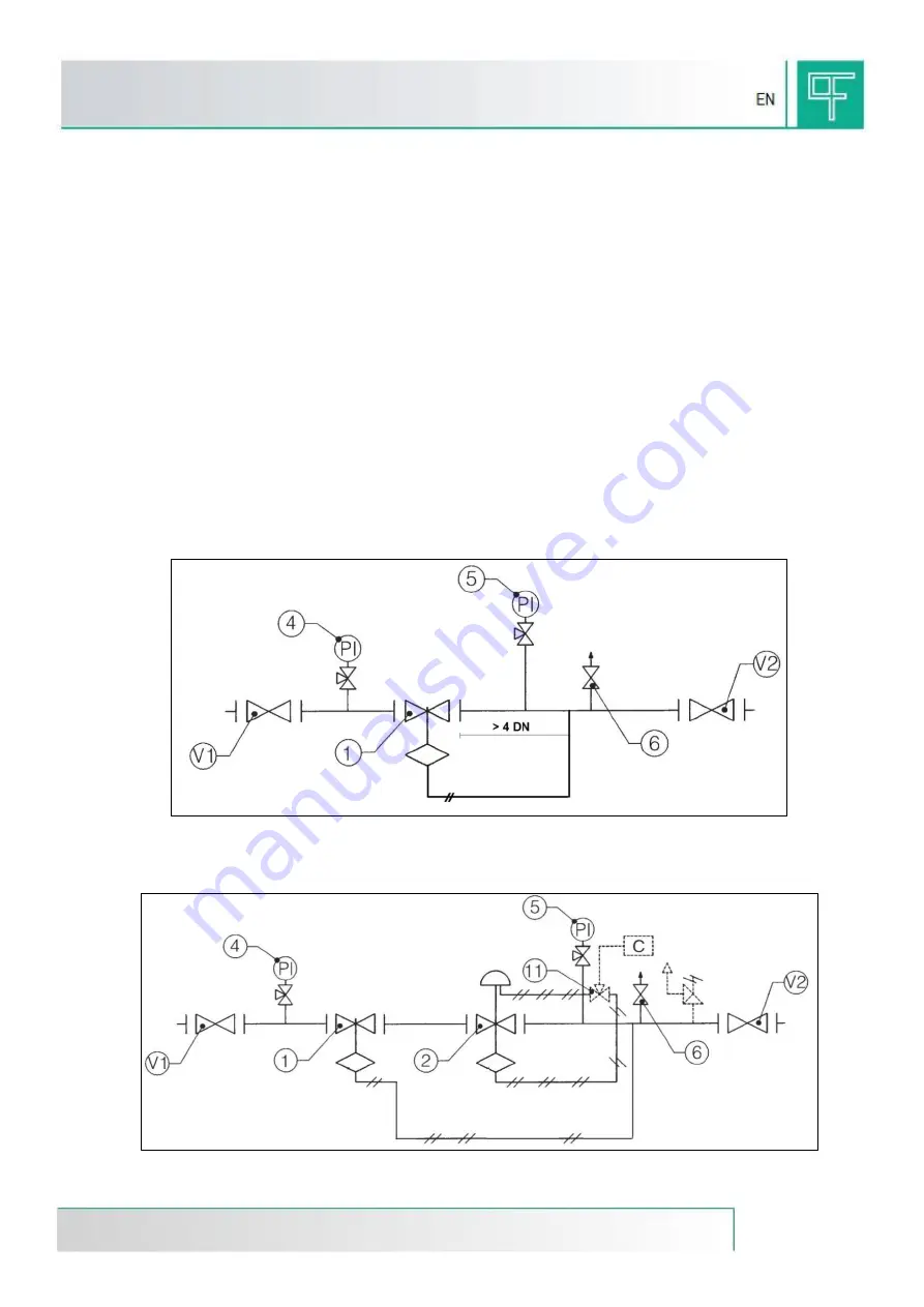
The most frequent types of installation on a gas pressure reduction line of the valve DILOCK are shown in the figures 4 and 5.
Installation of the valve on a piping segment
Figure 4: Installation diagram
Installation of the valve on a gas pressure reduction line as safety in case of fault of the pressure regulator
Figure 5: Installation diagram
Slam-shut
valve
Sensing line
Pressure gauge
Relief valve
On-off valve
Pressure gauge
On-off valve


