


Name
Description
Dimensions
Initials
Quantity
Half-shaft, trans-
mission side
13.75+0.040
C
clearance E = 0.25
to 0.50 - clearance
F = 0.20 to 0.75
Flywheel-side half-
shaft
13.75+0.040
D
clearance E = 0.25
to 0.50 - clearance
F = 0.20 to 0.75
Lining between the
shoulders
40.64
H
clearance E = 0.25
to 0.50 - clearance
F = 0.20 to 0.75
Cage
11.800-0.35
B
clearance F = 0.20
to 0.75
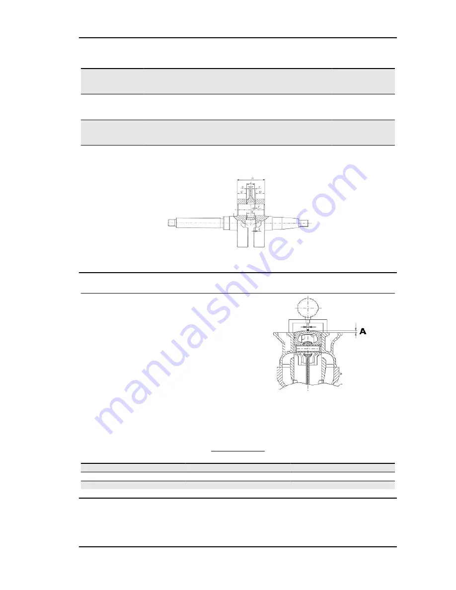
Slot packing system
- Fit the cylinder without installing the basic gasket.
- Apply a centimetre dial gauge on the special tool
and zero it on the ground plane
- Fit the tool to the top of the cylinder fixing it with
two nuts to the studbolts and take the piston to the
T.D.C.
- The thickness of the gasket to fit will change de-
pending on the value detected. For this purpose,
there are three with different thicknesses
Specific tooling
020272Y
Piston position check tool
S
HIMMING
SYSTEM
Name
Measure A
Thickness
Shimming
2.80 ÷ 3.04
0,4
Shimming
3.04 ÷ 3.24
0,6
Shimming
3.25 ÷ 3.48
0,8
NRG Power Purejet
Characteristics
CHAR - 9
Summary of Contents for NRG POWER PUREJET
Page 1: ...WORKSHOP MANUAL 633265 NRG Power Purejet...
Page 4: ......
Page 6: ......
Page 7: ...INDEX OF TOPICS CHARACTERISTICS CHAR...
Page 17: ...INDEX OF TOPICS TOOLING TOOL...
Page 29: ...INDEX OF TOPICS MAINTENANCE MAIN...
Page 39: ...INDEX OF TOPICS TROUBLESHOOTING TROUBL...
Page 45: ...INDEX OF TOPICS ELECTRICAL SYSTEM ELE SYS...
Page 62: ...Electrical system NRG Power Purejet ELE SYS 18...
Page 63: ...INDEX OF TOPICS ENGINE FROM VEHICLE ENG VE...
Page 65: ...INDEX OF TOPICS ENGINE ENG...
Page 106: ...Engine NRG Power Purejet ENG 42...
Page 107: ...INDEX OF TOPICS SUSPENSIONS SUSP...
Page 116: ...Suspensions NRG Power Purejet SUSP 10...
Page 117: ...INDEX OF TOPICS PURE JET INJECTION INJ PJ...
Page 180: ...pure jet injection NRG Power Purejet INJ PJ 64...
Page 181: ...INDEX OF TOPICS BRAKING SYSTEM BRAK SYS...
Page 189: ...INDEX OF TOPICS COOLING SYSTEM COOL SYS...
Page 195: ...INDEX OF TOPICS CHASSIS CHAS...
Page 200: ...Chassis NRG Power Purejet CHAS 6...
Page 201: ...INDEX OF TOPICS PRE DELIVERY PRE DE...
Page 205: ...INDEX OF TOPICS TIME TIME...