


MV-D752-28 User’s Manual
REV: 1.0
Page 45/61
15
Appendix C - RS232 Interface
The RS232 interface is a three-lead-interface (RX, TX, GND). This interface is often used
in industrial image processing for controlling camera settings. The cameras from
Photonfocus have an RS232 compatible interface. The following communication settings
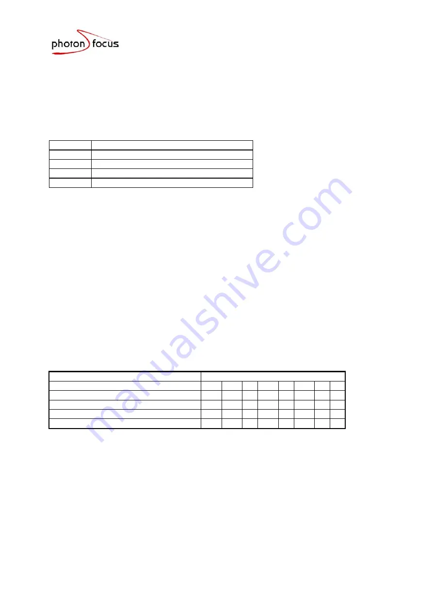
from the RS232 protocol have been chosen for the Photonfocus camera series:
Baud rate 9600
Start bit
1
data bits 8
Parity none
Stop bit
1
Through the selection of 8 data bits, it is possible to read one data byte with a single
shot. In the idle state the leads RX and TX are characterized by a
standard H-level
.
Data transfer begins with a
start bit
, which has a
L-level.
Afterwards the 8 data bits are
transmitted in the
sequence from D0…D7
. In order to separate subsequent data a stop
bit of
H-level
is added. The total number of cycles necessary for data transfer is 10.
After the data transfer, signals return to the idle state.
15.1
Definition of the transfer protocol
Due to the 8 bit RS232 limitation, it is not possible to distinguish between data and
address transfers. The protocol in Table 31 is implemented to allow access to the 64
internal camera registers.
Table 31: Communication protocol
RS232 Communication Protocol
Data bits
Command
to
camera
controller
7 6 5 4 3 2 1 0
WRITE
Address
0 1 A5 A4 A3 A2 A1 A0
WRITE Data Low Nibble
1
0
x
x D3 D2 D1 D0
WRITE Data High Nibble
1
1
x
x D7 D6 D5 D4
READ Data of Addresses
0
0 A5 A4 A3 A2 A1 A0
X: don’t
care
Ai: Address
bits
Dj: Data
bits
When data or addresses are written (WRITE Mode), the RS232 interface of the camera
answers with ACK = 06H, if the transfer was successful, or with NAK = 15H if the
transfer failed. Therefore it is possible to control the complete transfer process by the
software. When a register is read, the desired data is transmitted as a complete byte in
order to accelerate communication. Faulty data transmissions can only be recognized
using the stop bit. Additionally there are internal status registers (in the camera) which
record failures during transmission. An attempt to access an undefined camera register
will be answered with CAN = 18H. An overview over the camera feedback is shown
inTable 32.