Photon Focus DR1-D3360-192-G2-8 User Manual Download Page 110

8 Mechanical Considerations

8.2

Adjusting the Back Focus

The back focus of your Photonfocus camera is correctly adjusted in the production of the
camera.

This section describes the procedure to adjust the back focus if you require that because e.g.
you are using a special lens.

1.

Screw a lens strongly into the camera’s C-mount ring.

2.

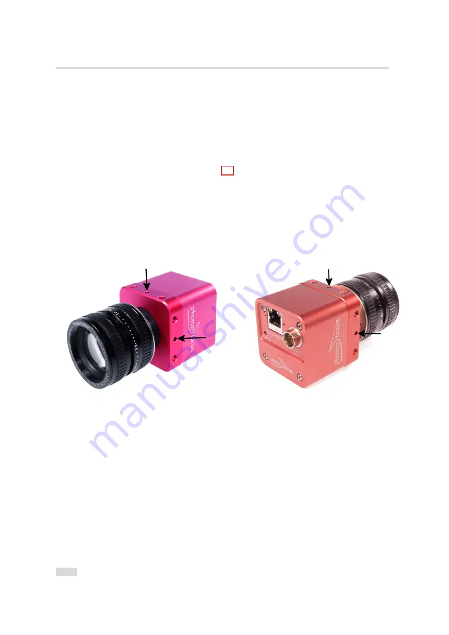
Unscrew the 3 small screws that lock the C-mount ring with a hex-wrench of size 0.89 mm.
The position of the screws is shown in Fig. 8.2. The ring can now be screwn upwards or
downwards by turning the lens.

3.

To adjust the back focus fully open the aperture of the lens and set the focus to infinite.

4.

Start the image acquisition and point the camera to a straight edge/line in a distance x (x
= infinite distance of your lens) from the camera, e.g. a door frame.

5.

Screw the ring upwards or downwards until the straight edge/line (distance: infinite) is
also straight on the camera image.

6.

Tighten the small screws. As the ring is locked, the lens can now be easily removed.

Figure 8.2: Position of the 3 small screws that lock C-mount ring

110

Summary of Contents for DR1-D3360-192-G2-8

Page 1: ...MAN071 03 2015 V1 0 Photonfocus MV1 D3360 G2 Camera Series CMOS camera with GigE interface...

Page 2: ...responsibility is assumed by Photonfocus AG for its use Photonfocus AG reserves the right to make changes to this information without notice Reproduction of this manual in whole or in part by any mean...

Page 3: ...CH 8853 Lachen SZ Switzerland Sales Phone 41 55 451 00 00 Email sales photonfocus com Support Phone 41 55 451 00 00 Email support photonfocus com Table 1 1 Photonfocus Contact 1 3 Sales Offices Photo...

Page 4: ...aving been obtained from Photonfocus AG Photonfocus can not be held responsible for any technical or typographical er rors 1 5 Legend In this documentation the reader s attention is drawn to the follo...

Page 5: ...a naming convention Prefix1 DR1 cameras have DR1 as Pre x1 whereas the other cameras have MV1 as Pre x1 Prefix2 Camera family speci er The following speci ers are used in this manual D standard area s...

Page 6: ...ture These cameras have Pre x2 D see also Fig 2 1 DR1 camera Camera that use a proprietary coding algorithm to double the maximal frame rate compared to a standard GigE camera over one GigE cable D xx...

Page 7: ...s guide the Intel PRO 1000 GT desktop adapter is used The descriptions in the following chapters assume that such a network interface card NIC is installed The latest drivers for this NIC must be inst...

Page 8: ...h e r n e t J a c k R J 4 5 P o w e r S u p p l y a n d I O C o n n e c t o r S t a t u s L E D Figure 3 1 Rear view of the Photonfocus GigE camera series with power supply and I O connector Ethernet...

Page 9: ...computer before proceeding 4 After the computer has been restarted open the eBUS Driver Installation tool Start All Programs eBUS SDK Tools Driver Installation Tool see Fig 3 2 If there is more than...

Page 10: ...3 How to get started GigE G2 Figure 3 3 PFInstaller components choice 10...

Page 11: ...tings are described in the tool chapter 1 Open the Network Connections window Control Panel Network and Internet Connections Network Connections right click on the name of the network adapter where th...

Page 12: ...ress automatically For this quick start guide it is recommended to con gure the network adapter to obtain an IP address automatically To do this select Internet Protocol TCP IP see Fig 3 4 click the P...

Page 13: ...ck on the Advanced tab and click on Jumbo Frames in the Settings list see Fig 3 6 The highest number gives the best performance Some tools however don t support the value 16128 For this guide it is re...

Page 14: ...ws Firewall is used then it can be switched off like this Open the Windows Firewall con guration Start Control Panel Network and Internet Connections Windows Firewall and click on the Advanced tab Unc...

Page 15: ...rk adapter where the Photonfocus camera is connected and select Properties from the drop down menu that appears A Properties window will open Check the eBUS Universal Pro Driver see Fig 3 8 for maxima...

Page 16: ...o acquire images from the camera and how to modify camera settings 1 Open the PF_GEVPlayer software Start All Programs Photonfocus GigE_Tools PF_GEVPlayer which is a GUI to set camera parameters and t...

Page 17: ...camera is not listed then select the box Show unreachable GigE Vision Devices Figure 3 10 GEV Device Selection Procedure displaying the selected camera 3 Select camera model to con gure and click on S...

Page 18: ...the con guration process and connect the camera to PF_GEVPlayer Figure 3 13 PF_GEVPlayer is readily configured 6 The camera is now connected to the PF_GEVPlayer Click on the Play button to grab image...

Page 19: ...ight is green when an image is being acquired and it is red when serial communication is active 8 Camera parameters can be modi ed by clicking on GEV Device control see Fig 3 15 The visibility option...

Page 20: ...3 How to get started GigE G2 9 To modify the exposure time scroll down to the AcquisitionControl control category bold title and modify the value of the ExposureTime property 20...

Page 21: ...21 1 fps 1680 x 2496 42 fps 840 x 2496 83 2 fps 420 x 2496 Frame rates of the DR1 192 cameras 21 1 fps 3360 x 2496 42 fps 1680 x 2496 83 2 fps 840 x 2496 Advanced I O capabilities 2 isolated trigger i...

Page 22: ...4 Product Speci cation Figure 4 1 Photonfocus D3360 GigE camera series with C mount lens 22...

Page 23: ...ed trigger input PLC Trigger Features Greyscale color resolution 10 bit 8 bit DR1 8 bit only Region of Interest ROI Up to 8 regions of interest MROI 2 look up tables 12 to 8 bit on user de ned image r...

Page 24: ...vailability MV1 D3360 96 G2 10 3360 x 2496 10 6 fps 1 n a no no released MV1 D3360C 96 G2 10 3360 x 2496 10 6 fps 1 n a no yes on request DR1 D3360 192 G2 8 3360 x 2496 21 1 fps 1 DoubleRate no no on...

Page 25: ...n 0 077 LSB e Sensitivity 5 56 V lux s with micro lenses 550 nm Optical ll factor 42 without micro lenses Dark current 41 2 e s 25 C Read out noise 8 6 e Dynamic range 61 dB Micro lenses Yes Color for...

Page 26: ...Maximal power consumption 12 V 5 1 W Lens mount C Mount CS Mount optional Dimensions 55 x 55 x 51 5 mm3 Mass 270 g Conformity RoHS WEEE Table 4 4 Physical characteristics and operating ranges Fig 4 2...

Page 27: ...s shown in Fig 4 4 Refraction index of the glass is 1 52 Scratch bubbles and digs shall be less than or equal to 0 02 mm 0 10 20 30 40 50 60 70 80 90 100 300 400 500 600 700 800 900 1000 1100 1200 Tra...

Page 28: ...ameras which is often denoted as Green Blue pattern The xed bayer pattern arrangement has to be considered when the ROI con g uration is changed or the MROI feature is used see Section 5 1 It depends...

Page 29: ...any rectangular window and is speci ed by its position within the full frame and its width W and height H The ROI width must be a multiple of 2 in the D cameras and a multiple of 32 in DR1 cameras The...

Page 30: ...0 1 0 6 f p s 1 6 8 0 8 4 0 2 1 1 f p s 0 2 0 4 0 6 0 8 0 4 2 f p s M V 1 D 3 3 6 0 C 9 6 G 2 1 0 0 4 2 0 8 3 2 f p s D R 1 D 3 3 6 0 C 1 9 2 G 2 d o u b l e r a t e e n a b l e d 2 1 1 f p s 4 2 f p...

Page 31: ...and columns being read out Overlapping ROIs are not allowed and no row must be read out more than once The individual ROI in a MROI must not overlap and no row should be included in more than one ROI...

Page 32: ...R O I x m a x y m a x R O I X R O I W R O I Y R O I H R O I X R O I W M R O I 0 Y M R O I 0 H M R O I 1 Y M R O I 1 H M R O I 2 Y M R O I 2 H 0 0 R O I W M R O I 0 H M R O I 1 H M R O I 2 H 0 0 R O I...

Page 33: ...fps DR1 192 double rate enabled can be achieved Without using MROI the resulting frame rate would be for a 636x1088 ROI 85 fps D 96 or 169 fps DR1 192 double rate enabled 6 3 6 p i x e l 0 0 x m a x...

Page 34: ...g if decima tion 3 then the height of every ROI should be a multiple of 3 Fig 5 5 shows decimation on the full image The rows that will be read out are marked by red lines Row 0 is read out and then e...

Page 35: ...0 0 x m a x y m a x R O I Figure 5 6 Decimation and ROI M R O I 0 R O I M R O I 2 M R O I 1 0 0 x m a x y m a x Figure 5 7 Decimation and MROI 5 1 Reduction of Image Size 35...

Page 36: ...asurement of the elongation of an injection needle is given in Fig 5 9 In this application the height information is less important than the width information Applying decimation 2 on the original ima...

Page 37: ...red rows The number of skipped rows for decimation d are Hskip d 1 2 The resulting number or rows for Window H h htot 2 floor h d min h mod 2 d 2 The total number of rows can be read by the property H...

Page 38: ...rt section of the Photonfocus web page www photonfocus com The maximal frame rate with the current camera settings can be read out by a camera register with p ib and it is also displayed in the PFRemo...

Page 39: ...T R e a d o u t D e l Figure 5 11 Simultaneous read out timing 1 exposure time smaller than read out time Simultaneous Read out Timing 2 The exposure time is bigger than the read out time in this timi...

Page 40: ...xposure time in external trigger mode can be de ned by the setting of the exposure time register camera controlled exposure mode or by the width of the incoming trigger pulse trigger controlled exposu...

Page 41: ...TriggerSource Line1 PLC_Q4 Trigger The trigger signal is applied by the Q4 output of the PLC see also Section 6 6 Settings for PLC_Q4 Trigger mode TriggerMode On and TriggerSource PLC_Q4 ABTrigger Tri...

Page 42: ...d to shoot images si multaneously If all cameras are set to Continuous mode then all will send the packets at same time resulting in network congestion A better way would be to set the cameras in Cont...

Page 43: ...d after n triggers have been accepted SingleFrameRecording Off Camera saves one image on the on board memory of the IP engine SingleFrameRecording On Camera is ready to accept one trigger according to...

Page 44: ...trolled exposure time e x t e r n a l t r i g g e r p u l s e i n p u t t r i g g e r a f t e r i s o l a t o r t r i g g e r p u l s e i n t e r n a l c a m e r a c o n t r o l d e l a y e d t r i g...

Page 45: ...l external strobe output is controlled by the rising edge of the trigger pulse Timing diagram Fig 5 17 shows the detailed timing for the external trigger mode with pulse width controlled exposure time...

Page 46: ...ogrammable delay delay from the active input trigger edge to the rising edge of the strobe output signal Strobe_PulseWidth Width of the trigger pulse in s A setting of 0 turns off the strobe output St...

Page 47: ...l i n t e r n a l s t r o b e c o n t r o l e x t e r n a l s t r o b e p u l s e o u t p u t t d i s o i n p u t t j i t t e r t t r i g g e r d e l a y t e x p o s u r e t s t r o b e d e l a y t d...

Page 48: ...d time depends on camera settings 0 35 s ttrigger offset non burst mode 166 ns duration of 1 row ttrigger offset burst mode 208 ns 208 ns texposure 26 s 0 35 s tstrobe delay 600 ns 0 35 s tstrobe offs...

Page 49: ...Suppresses the generation of triggers when the A B signal bounce ABTriggerDeBounce is ignored when ABTriggerDirection fwdbkwd ABTriggerDivider Speci es a division factor for the trigger pulses Value...

Page 50: ...uble A B mode and double the value of ABTriggerDivider A B G r a y C o u n t e r E n c o d e r C o u n t e r T r i g g e r F w d T r i g g e r B k w d 0 1 2 3 0 1 2 3 2 1 0 3 2 1 2 3 0 0 1 2 1 0 T r i...

Page 51: ...and retraces by a small amount which may cause a misalignment in the system If ABTriggerDirection fwd is used and the Debounce mode is enabled and the conveyor belt starts again in forward direction...

Page 52: ...TriggerAOnly is enabled then the encoder position is always incremented Detailed diagrams are shown in Fig 5 25 and Fig 5 26 Note that the quad mode is not available when ABTriggerAOnly true A E n c o...

Page 53: ...sed Burst Trigger Counter When the camera is in burst trigger mode see Section 5 2 7 a missed burst trigger counter will be incremented when a subsequent external trigger TriggerMode On is applied whi...

Page 54: ...precision of 30 ppm and therefore the values of the timestamp real time counter of the cameras may diverge with time If this is an issue then the counters could be reset periodically by the external...

Page 55: ...sponds to Vlow1 the higher the value the higher the compression Multislope_Time1 Time corresponding to kneepoint B The value is the fraction per mill of the total exposure time Multislope_Value2 Corre...

Page 56: ...l r e s e t K n e e p o i n t A K n e e p o i n t B M u l t i s l o p e _ T i m e 2 M u l t i s l o p e _ T i m e 1 E x p o s u r e T i m e Figure 5 27 Multi Slope Mode n u m b e r o f e l e c t r o n...

Page 57: ...i t a l O f f s e t D i g i t a l G a i n L o o k u p t a b l e L U T C r o s s h a i r s i n s e r t i o n S t a t u s l i n e i n s e r t i o n T e s t i m a g e s i n s e r t i o n A p p l y d a t...

Page 58: ...chieved working temperature 5 The image sensor must be uniformly illuminated to give an image with a mid grey level Check this before you proceed with the instructions 6 Set the visibility of the Devi...

Page 59: ...ility Although a new calibration is normally not required you can recalibrate the Column FPN Correction with the following instructions 1 Setup the camera to the mode where it will be usually used Exp...

Page 60: ...rmanent memory overwrites the factory calibration 5 7 Gain and Offset There are three different gain settings on the camera Analog Gain Analog gain on the image sensor only available in some models se...

Page 61: ...a are set to random values The output grey level resolution of the look up table independent of gain gamma or user de nded mode is always 8 bit There are 2 prede ned functions which generate a look up...

Page 62: ...00 1200 0 50 100 150 200 250 300 Grey level transformation Gain y 255 1023 a x x grey level input value 10 bit DN y grey level output value 8 bit DN a 1 0 a 2 0 a 3 0 a 4 0 Figure 5 31 Applying a line...

Page 63: ...00 800 1000 1200 0 50 100 150 200 250 300 Grey level transformation Gamma y 255 1023 x 1 x grey level input value 10 bit DN y grey level output value 8 bit DN 1 0 1 2 1 5 1 8 2 5 4 0 Figure 5 32 Apply...

Page 64: ...age X X LUT 0 active in Region 0 X X X LUT 0 active in Region 0 and LUT 1 active in Region 1 LUT 0 supersedes LUT1 Table 5 8 LUT Enable and Region LUT When Region LUT feature is enabled then the LUTs...

Page 65: ...0 x 1 0 x 0 1 x 1 1 y 1 0 y 0 0 y 0 1 y 1 1 Figure 5 35 Overlapping Region LUT example L U T 0 L U T 1 L U T 1 L U T 0 0 0 0 0 x m a x y m a x x m a x y m a x Figure 5 36 Region LUT in keyhole inspect...

Page 66: ...eft hand side The result of the application of the Region LUT is shown on the right hand side One Region LUT was applied on a small region on the lower part of the image where the brightness has been...

Page 67: ...el to get the maximum contrast depending on the acquired image The x y position and the grey level can be set via the camera software Figure Fig 5 38 shows two examples of the activated crosshairs wit...

Page 68: ...n both situations The crosshairs however is set differently The crosshairs is not seen in the image on the right because the x and y position is set outside the MROI region 0 0 x a b s o l u t y a b s...

Page 69: ...a start and counts real time in units of 1 micro second The time counter can be reset by the software in the SDK Counter width 32 bit Missed trigger counter The missed trigger counter counts trigger p...

Page 70: ...eld is 32 bit see Fig 5 40 The assignment of the parameters to the elds is listed in Table 5 9 The status line is available in all camera modes 4 8 1 2 1 6 2 0 P r e a m b l e F i e l d 0 0 P i x e l...

Page 71: ...rce 0 TriggerMode Off 1 TriggerMode On TriggerSource PLC_Q4 2 TriggerMode On TriggerSource Line1 3 TriggerMode On TriggerSource Software 4 TriggerMode On TriggerSource ABTrigger 52 2 Digital Gain 56 2...

Page 72: ...5 10 3 Camera Type Codes Camera Model Camera Type Code MV1 D3360 96 G2 10 434 MV1 D3360C 96 G2 10 435 DR1 D3360 192 G2 8 TBD DR1 D3360C 192 G2 8 TBD Table 5 10 Type codes of Photonfocus D3360 GigE ca...

Page 73: ...t output left 10 bit output right 5 11 2 LFSR The LFSR Linear Feedback Shift Register test image outputs a constant pattern with a pseudo random grey level sequence containing every possible grey leve...

Page 74: ...non at histogram Fig 5 44 indicates problems that may be caused either by a defective camera by problems in the acquisition software or in the transmission path Figure 5 43 LFSR test pattern received...

Page 75: ...measuring tasks where sub pixel precision is required Double rate modulation can be turned off for debugging purposes The encoded image is transmitted in mono 8 bit data resolution The encoding is run...

Page 76: ...5 Functionality 76...

Page 77: ...which indicates camera operation E t h e r n e t J a c k R J 4 5 P o w e r S u p p l y a n d I O C o n n e c t o r S t a t u s L E D Figure 6 1 Rear view of the GigE camera 6 2 Power Supply Connector...

Page 78: ...links at a rate equal to the frame rate At slow frame rates the LED blinks At high frame rates the LED changes to an apparently continuous green light with intensity proportional to the ratio of reado...

Page 79: ...E l e c t r o n i c I S O L A T O R I S O _ G N D I S O _ P W R 1 2 1 2 p o l H i r o s e C o n n e c t o r 6 8 3 9 7 1 0 1 1 4 5 I O a n d T r i g g e r I n t e r f a c e D C D C D C D C V C C _ 2 V...

Page 80: ...me power supply within a range between 10 and 30V In the same way encoder ground HTL_ENC_GND and ISO_GND signals should be connected to the same ground in order to guarantee the good reception of the...

Page 81: ...T 0 P T C 4 k 7 M a x 3 0 V M a x 0 5 A M a x 0 5 W I S O _ G N D P o w e r M O S F E T I S O _ O U T 1 P T C M a x 3 0 V M a x 0 5 A M a x 0 5 W I s o l a t e d I n t e r f a c e C a m e r a E l e c...

Page 82: ...M O S F E T I S O _ O U T 0 P T C 4 k 7 M a x 3 0 V M a x 0 5 A M a x 0 5 W I S O _ G N D P o w e r M O S F E T I S O _ O U T 1 P T C M a x 3 0 V M a x 0 5 A M a x 0 5 W I s o l a t e d I n t e r f a...

Page 83: ...I S O _ I N 0 C a m e r a 7 1 2 p o l H i r o s e C o n n e c t o r I S O _ G N D 1 2 Y O U R _ G N D Y O U R _ G N D I n p u t V o l t a g e M a x 3 0 V D C M i n 3 0 V D C Figure 6 5 Direct connect...

Page 84: ...E T I S O _ O U T 0 P T C 4 k 7 C a m e r a 3 1 2 p o l H i r o s e C o n n e c t o r I S O _ G N D 1 2 Y O U R _ G N D I S O _ P W R Y O U R _ P W R Y O U R _ G N D C o n t r o l L o g i c Y O U R _...

Page 85: ...atings that must not be exceeded voltage 30 V current 0 5 A power 0 5 W see also Fig 6 10 The type of the Power MOSFET is International Recti er IRLML0100TRPbF Y O U R _ P W R I S O _ G N D P o w e r...

Page 86: ...e r a Figure 6 11 Incorrect connection to ISO_INC inputs 6 5 5 Master Slave Camera Connection The trigger input of one Photonfocus G2 camera can easily connected to the strobe output of another Photon...

Page 87: ...mon power supply for camera and I O signals with star wiring Separate Grounds To separate the signal and ground connections of the camera CAM_GND CAM_PWR data connections from the I O connections ISO_...

Page 88: ...tic of the star wiring concept applied to a Photonfocus GigE camera The power supply and ground connections for the camera and for the I O are connected to the same power supply which acts as the Star...

Page 89: ...d cables are connected to the same power supply P o w e r S u p p l y C a m e r a F l a s h M a c h i n e V i s i o n S y s t e m P C E t h e r n e t D a t a C a b l e S T R C A M _ P W R C A M _ G N...

Page 90: ...G N D a n d I S O _ G N D t h e w r o n g w a y G r o u n d l o o p G r o u n d l o o p Figure 6 17 Improper I O wiring causing a ground loop 6 6 PLC connections The PLC Programmable Logic Controller...

Page 91: ...gnal A7 camera head PLC Reserved CL_SPARE Q0 PLC not connected Q1 PLC power connector ISO_OUT1 output signal signal is inverted Q2 PLC not connected Q3 PLC not connected Q4 PLC camera head PLC_Q4 came...

Page 92: ...6 Hardware Interface 92...

Page 93: ...be selected in the installation of the PFInstaller DR1_Tools support for DR1 cameras and Halcon Extensions In the next step the correct HALCON version 10 or 11 must be selected 7 2 PF_GEVPlayer The ca...

Page 94: ...et properties of the camera head IP properties and properties of the PLC Programmable Logic Controller see also Section 6 6 and document PLC Image stream control Set image stream properties and displa...

Page 95: ...control window to apply the property value to the camera A red cross at the upper right corner of the GEV Control Window indicates a parameter error i e a parameter is not correctly set In this case y...

Page 96: ...ects all colors equally e g a special grey reference card while clicking on the White Balance button The white balance settings that were made as described in this section are ap plied by the PF_GEVP...

Page 97: ...Installer that can be downloaded from the Photonfocus webpage The following list shows some frequently used properties that are available in the Beginner mode The category name is given in parenthesis...

Page 98: ...et properties LUT_X LUT_W LUT_Y and LUT_H all in category RegionLUT to desired value 5 Set LUT content as described in Section 7 5 4 6 If two Region LUT are required then select LUT 1 by setting LUTSe...

Page 99: ...setting MROI_Enable to False This is mandatory otherwise setting the MROI entries will be ignored 2 Set MROI_Index In the rst run it is set to 0 and then incremented in every run 3 Set MROI_Y to the s...

Page 100: ...in the ash memory It is recommended to use UserSetSave instead as all properties are stored The calibration values of the FPN calibration are not stored with UserSetSave or CameraHeadStoreDefaults Us...

Page 101: ...b l e I 1 I 2 I 3 I 4 I 5 I 6 I 7 I 0 E n h a n c e d F u n c t i o n B l o c k Q 0 Q 1 Q 2 Q 3 Q 4 Q 5 Q 6 Q 7 Q 8 Q 9 Q 1 0 Q 1 1 Q 1 5 Q 1 6 Q 1 7 R e m o t e C o n t r o l B l o c k f r o m h o s...

Page 102: ...s are ignored by setting the PLC_Q4_Variable to Zero and the PLC_Q4_Operator to Or for inputs 1 to 3 5 If a PLC output is used to connect to a camera trigger then the corresponding Trigger Source must...

Page 103: ...ock PLC_I3 Line3 PLC SignalRoutingBlock PLC_Q6_Variable0 PLC_I2 PLC LookupTable Q6 PLC_Q6_Operator0 Or PLC LookupTable Q6 PLC_Q6_Variable1 Zero PLC LookupTable Q6 PLC_Q6_Operator1 Or PLC LookupTable Q...

Page 104: ...ngBlock PLC_I1 Line1 PLC SignalRoutingBlock PLC_Q6_Variable0 PLC_I0 PLC LookupTable Q6 PLC_Q6_Operator0 Or PLC LookupTable Q6 PLC_Q6_Variable1 Zero PLC LookupTable Q6 PLC_Q6_Operator1 Or PLC LookupTab...

Page 105: ...no10Packed BayerGB10Packed 12 Mono12 BayerGB12 16 Mono12Packed BayerGB12Packed 12 Mono16 16 Table 7 4 GigE pixel format overview The DR1 color camera models have the BayerGB8 format This should be use...

Page 106: ...all colors equally e g a special grey reference card 4 Do a white balancing in the PF_GEVPlayer as described in Section 7 2 4 5 Copy the values to the camera DigitalGain settings i e copy the value o...

Page 107: ...dll from the PFInstaller Rev 2 38 and later The whole image including the status line can be applied to the demodulation functions The status line is copied unmodi ed to the demodulated image which i...

Page 108: ...e can be selected by clicking on the button Select Output File This is the resulting le after modulation and demodulation of the input image Additionally a difference le can be generated by enabling t...

Page 109: ...o local regulations 8 1 1 Cameras with GigE Interface Fig 8 1 shows the mechanical drawing of the camera housing for the Photonfocus D3360 GigE camera series 55 55 20 12 8 25 4 36 6 41 3 5 51 5 8x M5...

Page 110: ...tion of the screws is shown in Fig 8 2 The ring can now be screwn upwards or downwards by turning the lens 3 To adjust the back focus fully open the aperture of the lens and set the focus to in nite 4...

Page 111: ...the manufacturer and accompanying said product and the product shall be free from defects in materials and workmanship under normal use The distributor shall not make or pass on to any party any warra...

Page 112: ...9 Warranty 112...

Page 113: ...www photonfocus com GEVQS GEVPlayer Quick Start Guide Pleora Technologies Included in eBUS installer MAN051 Manual Photonfocus GigE Quick Start Guide Photonfocus PLC iPORT Programmable Logic Controll...

Page 114: ...10 References 114...

Page 115: ...your camera Incorrect voltages will damage or destroy the camera The connection of the input and output signals is described in Section 6 5 A suitable power supply can be ordered from your Photonfocus...

Page 116: ...WR Power supply 5V 24V for output signals Do NOT connect to camera Power 7 I ISO_IN0 IN0 input signal 8 O ISO_OUT1 MISC Q1 output from PLC no Pull up to ISO_PWR can be used as additional output by add...

Page 117: ...B Camera Revisions B 1 General Remarks This chapter lists differences between the revisions of the camera models 117...

Page 118: ...2 V1 0 ROI yes yes Double Rate no yes MROI yes yes Decimation yes yes Standard Trigger yes yes AB Trigger yes yes Counter Reset External yes yes ResetCounter_Dual yes yes Multiple Slope yes yes Bad Pi...

Page 119: ...C Document Revision History Revision Date Changes 1 0 March 2016 First version 119...

Reviews: