


PIN
IO
Name
Description
1
PW
SHIELD
Shield
2
O
N_XD0
Negative LVDS Output, CameraLink
®
Data D0
3
O
N_XD1
Negative LVDS Output, CameraLink
®
Data D1
4
O
N_XD2
Negative LVDS Output, CameraLink
®
Data D2
5
O
N_XCLK
Negative LVDS Output, CameraLink
®
Clock
6
O
N_XD3
Negative LVDS Output, CameraLink
®
Data D3
7
I
P_SERTOCAM
Positive LVDS Input, Serial Communication to the camera
8
O
N_SERTOFG
Negative LVDS Output, Serial Communication from the camera
9
I
N_CC1
Negative LVDS Input, Camera Control 1 (CC1)
10
I
N_CC2
Positive LVDS Input, Camera Control 2 (CC2)
11
I
N_CC3
Negative LVDS Input, Camera Control 3 (CC3)
12
I
P_CC4
Positive LVDS Input, Camera Control 4 (CC4)
13
PW
SHIELD
Shield
14
PW
SHIELD
Shield
15
O
P_XD0
Positive LVDS Output, CameraLink
®
Data D0
16
O
P_XD1
Positive LVDS Output, CameraLink
®
Data D1
17
O
P_XD2
Positive LVDS Output, CameraLink
®
Data D2
18
O
P_XCLK
Positive LVDS Output, CameraLink
®
Clock
19
O
P_XD3
Positive LVDS Output, CameraLink
®
Data D3
20
I
N_SERTOCAM
Negative LVDS Input, Serial Communication to the camera
21
O
P_SERTOFG
Positive LVDS Output, Serial Communication from the camera
22
I
P_CC1
Positive LVDS Input, Camera Control 1 (CC1)
23
I
N_CC2
Negative LVDS Input, Camera Control 2 (CC2)
24
I
P_CC3
Positive LVDS Input, Camera Control 3 (CC3)
25
I
N_CC4
Negative LVDS Input, Camera Control 4 (CC4)
26
PW
SHIELD
Shield
S
PW
SHIELD
Shield
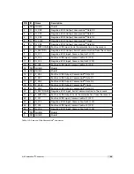
Table A.3: Pinout of the CameraLink
®
connector
.
A.2 CameraLink
®
Connector
99
Summary of Contents for D-2048 CameraLink Series
Page 1: ...User Manual Photonfocus D L 2048 CameraLink Series CMOS Area Scan Camera MAN054 11 2013 V1 3...
Page 2: ......
Page 4: ...2...
Page 8: ...CONTENTS 6...
Page 16: ...3 How to get started CameraLink Figure 3 4 PFRemote start window 14...
Page 92: ...8 Graphical User Interface GUI 90...
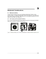
Page 94: ...9 Mechanical Considerations 92...
Page 96: ...10 Warranty 94...
Page 98: ...11 References 96...
Page 102: ...A Pinouts 100...
Page 108: ...B Camera Revisions 106...


