


A Pinouts
1
2
3
4
5
6
7
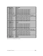
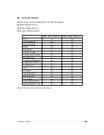
Figure A.2: Power supply plug, 7-pole (rear view of plug, solder side)
Pin
I/O Type
Name
Description
1
PWR
VDD
+12 V DC (
±
10%)
2
PWR
GND
Ground
3
O
RESERVED
Do not connect
4
PWR
STROBE-VDD
+5 .. +15 V DC
5
O
STROBE
Strobe control (opto-isolated)
6
I
TRIGGER
External trigger (opto-isolated), +5 .. +15V DC
7
PWR
GROUND
Signal ground (for opto-isolated strobe signal)
Table A.2: Power supply plug pin assignment
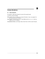
A.2
CameraLink
®
Connector
The pinout for the CameraLink
®
26 pin, 0.5" Mini D-Ribbon (MDR) connector is according to
the CameraLink
®
standard ([CL]) and is listed here for reference only (see Table A.3). The
drawing of the CameraLink
®
cable plug is shown in Fig. A.3.
CameraLink
®
cables
can
be
purchased
from
Photonfocus
directly
(www.photonfocus.com).
2
1
3
4
5
6
7
8
9
1 0
1 1
1 2
1 3
1 4
1 5
1 6
1 7
1 8
1 9
2 0
2 1
2 2
2 3
2 4
2 5
2 6
Figure A.3: CameraLink cable 3M MDR-26 plug (both ends)
.
98
Summary of Contents for D-2048 CameraLink Series
Page 1: ...User Manual Photonfocus D L 2048 CameraLink Series CMOS Area Scan Camera MAN054 11 2013 V1 3...
Page 2: ......
Page 4: ...2...
Page 8: ...CONTENTS 6...
Page 16: ...3 How to get started CameraLink Figure 3 4 PFRemote start window 14...
Page 92: ...8 Graphical User Interface GUI 90...
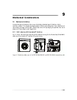
Page 94: ...9 Mechanical Considerations 92...
Page 96: ...10 Warranty 94...
Page 98: ...11 References 96...
Page 102: ...A Pinouts 100...
Page 108: ...B Camera Revisions 106...


