background image

21

22

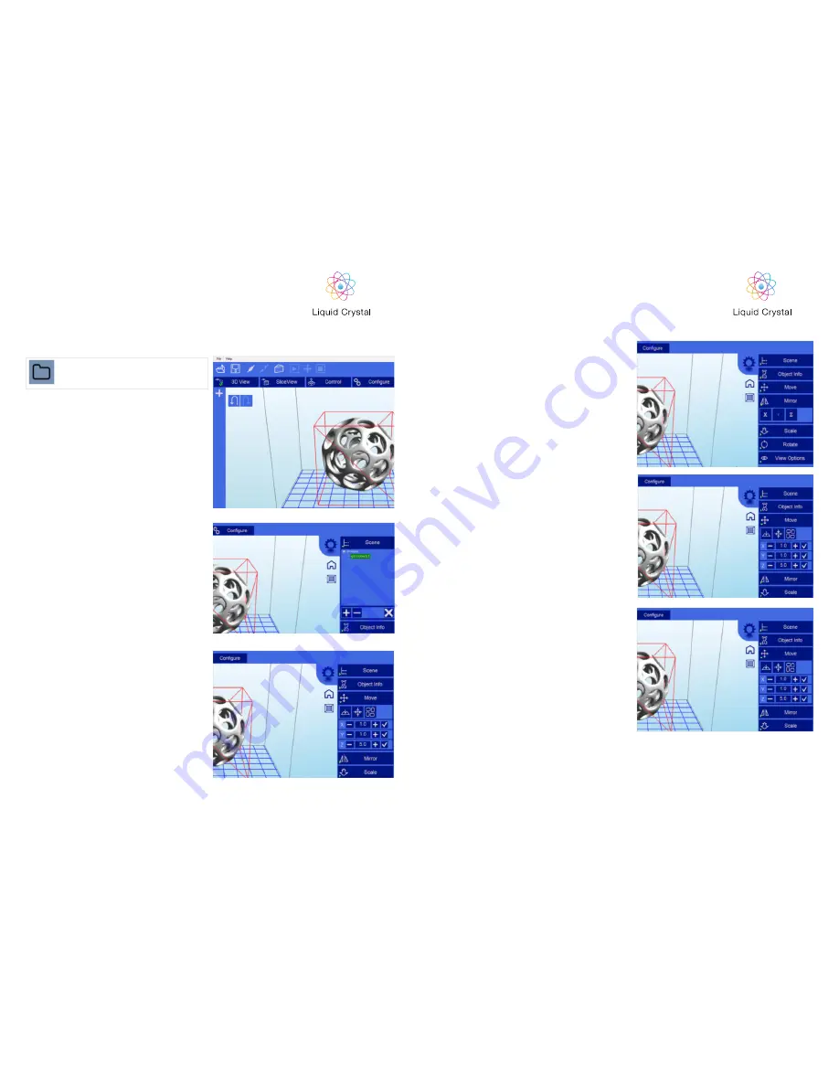
1. Loading a Model

The Scene View allows you to manipulate various 
aspects of the scene. 

Selecting 

You can select a model by double clicking on the 
model, or selecting it with the scene view  

Removing a Model 

You can remove a model by right-clicking on the 
name in the scene graph and selecting “Remove”.
The Minus sign “-” will also remove the current 
model. You can also delete a model by selecting 
it and then pressing the “delete” key on your 
keyboard.

Cloning a model

You can select a model in the scene and click the 
“+” sign to clone it. The cloned object will appear 

 2. Scene View

Click here to ‘Load’ your file. Multiple objects 
can be loaded and manipulated independently. 
You can also open scene files with the .CWS 
extension.

3. Object Info

4. Move View 

The Move function allows you to move objects 
on the build platform along the x:y:z axis by the 
distance entered.

From left to right, the other tools are:


The ‘Place on Platform’ button will position the 
bottom of the model to rest on the bottom of the 
build platform.
The ‘Center’ button will center the model at (0,0,0).

• Auto-Arrange will automatically lay out all 

models  to fit on the build platform. Any model 
that does not fit within the build platform will be 
moved outside the build area.

This tabs provides you with information about your 
model

A model can be scaled (reduced or increased) by 
selecting it, and using the ‘Scale’ view to enter in a 
new scaler value. Press the tick button to re-scale 
your object.

6. Scaling objects 

7. Rotating Objects

8. View Options 

Rotating a model works in a similar way to moving 
a model. Simply select the model you want to 
work with, and use the X/Y/Z +/- buttons to rotate 
the model by your specified degrees.

The view option allows you to manipulate various 
views and models.

On the top row from left to right:

•  50% Alpha-Blending toggle. This will allow 

you to see through the objects in the scene to 
see the geometry

•  Show Slice Preview on Scene. After slicing 

this toggles on/off the view of the 3D view 
of the current slice layer as selected by the 
horizontal scrollbar.

•  Show Console. This toggle button shows or 

hides the debug window. This window is used 
for debugging purposes.

On the bottom row from left to right are tools 

to change the way the objects appear on the 
screen:

•  Show objects with a bounding box.

The Mirror view allows you to mirror the selected 
object on the specified axis.

5. Mirroring Objects  

PRECISION

PRECISION

Summary of Contents for LC Precision

Page 1: ...d com www photocentric3d com UK USA DISPOSAL INSTRUCTIONS Do not throw this electronic device into the waste when discarding To minimize pollu tion and ensure utmost protection of the global environme...

Page 2: ...ftware Installation 2 Homing Procedure 3 Starting a Test Print 4 Washing 5 Hardening 6 Preparing for the next print 7 Re Skinning the Vat 8 Printing your own parts 9 Detailed Creation Workshop softwar...

Page 3: ...ogy i Low cost We use high resolution low cost LCD screens that are widely available in monitors tablets mobile phones and televisions These provide phenomenal value for money which we pass onto you i...

Page 4: ...clean off any resin spills Disconnect the printer from AC before storage or when not used for a long period of time This 3D printer is connected to the electrical net work with an input of 110 or 240...

Page 5: ...box 3 Open up the printer package remove the hood and then remove the printer 4 Place the printer in the work area Make sure the printer stands level and stable on four feet If it is not level you can...

Page 6: ...his can be checked by gently tapping on the film with your finger not your fingernail 1 Go to www photocentricgroup com and download the Liquid Crystal Precision Driver and Creation Workshop for Liqui...

Page 7: ...till find difficulties please contact your national supplier or contact us at info photocentric co uk 9 10 Ensure that the screen is clean wipe with a little liquid soap and warm water if it s dirty a...

Page 8: ...at this stage pressing the Show calibration button lo cated and a blue grid will appear To turn off the backlight send M107 command Now you have set up your printer lets make your first print 3 START...

Page 9: ...detergent Likewise you can use a hot soapy water spray to make sure excess resin has been cleaned from detailed areas To avoid a fragile part being damaged you can hold the part under running hot wat...

Page 10: ...rently taped to the vat and dispose of it It may be possible to use the double sided tape again if it has no resin on it If the tape cannot be reused remove it completely and replace on the lower edge...

Page 11: ...area check the settings of the printing profile Go to the Configure screen and open the Configure Slicing Profile tab Select the printing profile from the Machine Profiles list that matches your resi...

Page 12: ...er with supports and positioning These three buttons start pause and stop a print These buttons only become active once you have sliced your object Clicking this button allows you to view the 3D objec...

Page 13: ...all models to fit on the build platform Any model that does not fit within the build platform will be moved outside the build area This tabs provides you with information about your model A model can...

Page 14: ...ck the boxes under support general and generate only on downward Adaptive supports You can add supports to areas in the model that are unsupported There are 2 algorithms to help you accomplish this Th...

Reviews: