background image

7

MU1202 / MU1202X

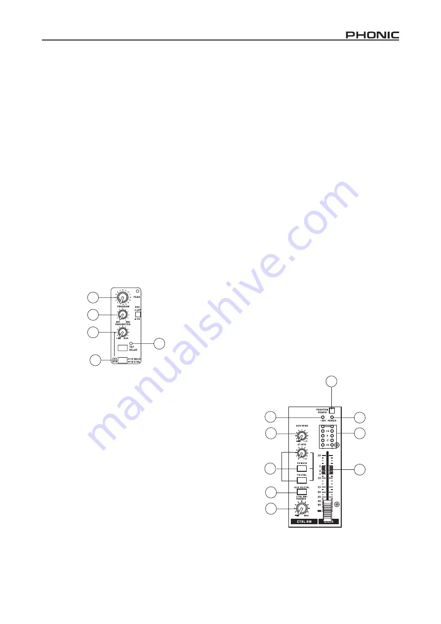
Digital Effect Section (MU1202X only)

22.  Program Control

This control is used to scroll through the various effects. Turning 

the control clockwise will allow users to ascend into higher pro-

gram numbers, and turning it counter-clockwise will allow users 

to descend into lower program numbers. 

23. Tap Delay Button and Indicator

When the tap delay effect is selected, this button will allow users 

to select the length at which the delay will occur.  The LED indica-

tor that accompanies it will flash at the intervals selected.

24.  Parameter Control

Turning this control will adjust the main paramter of the select-

ed effect.  For more information on effect parameters and their 

range, please consult the digital effects table.

25. EFX Level Control

Use this control to adjust the final output level from the EFX pro

-

cessor that is sent to the main or control room mix (depending on 

the "to Main/Control Room" switch).  Turn this control all the way 

to the left to effectively mute the EFX signal.

26.  EFX “to Main/to Control Room” Button

This  button  will  select  the  destination  of  the  processed  signal 

sent from the digital effect processor.  Users are able to select 

the Control Room mix or their Main mix as the destination for this 

EFX signal.

Master Section 

27.  Phantom Power Switch

When  this  switch  is  in  the  on  position,  it  activates  +48V  of 

phantom  power  for  all  microphone  inputs,  allowing  condenser 

microphones  (well,  the  ones  that  don’t  use  batteries)  to  be 

used  on  these  channels.  Activating  Phantom  Power  will  be 

accompanied by an illuminated LED above the left channel Level 

Meter. Before turning Phantom Power on, turn all level controls 

to a minimum to avoid the possibility of a ghastly popping sound 

from the speakers.

NB. 

Phantom  Power  should  be  used  in  conjunction  with  balanced 

microphones.  When  Phantom  Power  is  engaged,  single  ended 

(unbalanced)  microphones  and  instruments  should  not  be  used  on  the 

Mic  inputs.  Phantom  Power  will  not  cause  damage  to  most  dynamic 

microphones,  however  if  unsure,  the  microphone’s  user  manual  should 
be consulted.

28.  AUX Send Control (MU1202 only)

This  control  adjusts  the  final  level  of  the AUX  mixing  bus  (as 

taken from the AUX controls on each channel strip), the audio 

of which is sent to the AUX Send output (and sent to the Control 

Room/Phones output when the AUX to Ctrl button is engaged).

29.  2T Return Routing Buttons

These two buttons allow users to decide the destination of the 

signal  received  by  the  RCA  2T  Return  inputs.  The  “to  Main” 

button sends the signal to the main mix, whereas the “to Ctrl Rm” 

sends the signal to the Control Room mixing bus for monitoring.

30.  AUX “to Ctrl” Button (MU1202 only)

When this button is activated, the AUX send signal (the level of 

which  is  decided  by  the AUX  send  control)  will  be  sent  to  the 

Control Room mixing bus for monitoring purposes.

31.  Ctrl Rm / Phones Control

This  control  is  used  to  adjust  the  audio  level  of  the  Control 

Room  feed,  which  is  sent  to  both  the  Control  Room  outputs 

(for  monitoring,  acting  as  side  fill  or  other  purposes)  and 

Phones outputs (to be used in conjunction with headphones for 

monitoring).

32.  Main L-R Control

This 60mm fader is final level control for the main left and right 

audio feed, sent to the Main L and R outputs.

33.  Level Meter

The  MU  ’s  stereo  4-segment  level  meter  gives  an  accurate 

indication  of  when  audio  levels  of  the  MAIN  L/R  output  reach 

certain levels. It is suggested for the maximum use of audio to 

set the various levels controls to a level slightly below that which 

would cause the Peak LED to light up. This will help you get the 

most out of your audio without causing any distortion.

34.  +48 Indicator

The +48 Indicator illuminates whenever the Phantom Power is 

activated.

35.  Power Indicator

The Power Indicator will light up when the power of the mixer 

is on.

24

22

23

25

26

27

29

35

31

33

28

34

32

30 

Summary of Contents for mu1202

Page 1: ...User s Manual Manual del Usuario MU1202 MU1202X COMPACT MIXERS MEZCLADORAS COMPACTAS MU1202X English Espa ol...

Page 2: ...COMENZANDO 11 CONFIGURACI N DE CANAL 11 HACIENDO CONEXIONES 12 CONTROLES Y CONFIGURACIONES 13 ESPECIFICACIONES 15 TABLA DE EFECTO DIGITAL 23 APLICACI N 24 DIMENSIONES 25 DIAGRAMAS DE BLOQUE 26 CONTEN...

Page 3: ...hting storms or when unused for long periods of time 14 Refer all servicing to service personnel Servicing is required when the apparatus has been damaged in any way such as power supply cord or plug...

Page 4: ...elay Separate EFX route control GETTING STARTED 1 Ensure all power is turned off on your mixer To totally ensure this the power supply should not be connected to the unit 2 All faders and level contro...

Page 5: ...onnect to an external digital effect processor or even to an amplifier and speakers depending on your desired settings to the mixer The signal sent from these outputs is fed from the AUX send control...

Page 6: ...n the main mixing panel This signal is then sent to the AUX Send output which can be used in conjunction with an amplifier and studio or stage monitors or simply as an auxiliary output for any means r...

Page 7: ...m Power is engaged single ended unbalanced microphones and instruments should not be used on the Mic inputs Phantom Power will not cause damage to most dynamic microphones however if unsure the microp...

Page 8: ...nse Mic input to any output 20Hz 60KHz 0 1 dB 0 1 dB 20Hz 100KHz 0 3 dB 0 3 dB Crosstalk 1KHz 0dBu 20Hz to 20KHz bandwidth channel in to main L R outputs Channel fader down other channels at unity 90...

Page 9: ...80 Hz Mid EQ 2 5 KHz 2 5 KHz Hi EQ 12 KHz 12 KHz Low Cut Filter 75Hz 18dB oct 75Hz 18dB oct Effect Processor N A 16 effects with one main parameter control Power Requirement external power supply depe...

Page 10: ......

Page 11: ...ENZANDO 1 Aseg rese que todas las energ as en su mezcladora est n apagadas Para estar seguro totalmente el suministro de energ a no deber a estar conectado a la unidad 2 Todos los deslizadores y contr...

Page 12: ...terno o a un amplificador y altavoces dependiendo de sus configuraciones deseadas a la mezcladora La se al enviada desde estas salidas es alimentada de control de env o AUX en MU1202 y de Procesador d...

Page 13: ...Esta se al es entonces enviada a la salida de Env o AUX que puede ser utilizada junto con un amplificador y monitores de estudio y de escenario o simplemente como una salida auxiliar como sea requeri...

Page 14: ...orear actuar como relleno lateral u otros prop sitos y a las salidas Phones para ser utilizada junto con auriculares para el monitoreo 32 Control Principal I D Este deslizador de 60mm es el control de...

Page 15: ...zador 60mm Medidor de Nivel 2 x 4 segmentos 2 x 4 segmentos Suministro de Fuente Fantasma 48 VDC 48 VDC Respuesta en Frecuencia Entrada Mic a cualquier salida 20Hz 60KHz 0 1 dB 0 1 dB 20Hz 100KHz 0 3...

Page 16: ...K ohms 10 K ohms Salida RCA 2T 1 1 K ohms 1 1 K ohms Ecualizaci n 3 bandas 15dB 3 bandas 15dB EQ Bajo 80 Hz 80 Hz EQ Medio 2 5 KHz 2 5 KHz EQ Alto 12 KHz 12 KHz Filtro de Corte Bajo 75Hz 18dB oct 75H...

Page 17: ...1 2 3 4 5 6 7 8 9 10 11 12 13 14 CAUTION RISK OF ELECTRIC SHOCK DO NOT OPEN PHONIC CORPORATION...

Page 18: ...18 MU1202 MU1202X Phonic MU1202 1202X 4 4 AUX EFX 75Hz 3 48V EFX AUX Send Cue TRS MU1202X 32 40 16 EFX 1 AC 2 3 4 AC AC 5 1 2 3 0dB 4 5 0dB 6 7...

Page 19: ...MU1202X 5 Phones Control Room Phones 6 Main L Main R Main Main Output 7 1 4 Phone Control Room Phones 8 RCA MD 9 2T RCA CD Main L R 10 11 12 MU1202 MU1202X 4 13 12KHz 15dB 14 2 5KHz 15 dB 15 80Hz 15dB...

Page 20: ...n L Main R 33 MU1202 MU1202X 4 Main L R PEAK LED 34 48 48V 35 18 PAN BAL BALANCE 19 PEAK 6dB LED 20 21 4 10 MU1202 MU1202X 10dBV 4dBV MU1202X 22 23 LED 24 25 EFX EFX to Main to Control Room EFX 26 EFX...

Page 21: ...60mm Main L R 60mm 2 x 4 2 x 4 48V DC 48V DC 20Hz 60KHz 0 1 dB 0 1 dB 20Hz 100KHz 0 3 dB 0 3 dB 1KHz 0dBu 20Hz to 20KHz Main L R 90 dB 90 dB 20Hz 20KHz Main Output 1 4 EQ Main Mix 1 3 2 4 6d Bu 86 5 d...

Page 22: ...15 dB 80 Hz 80 Hz 2 5 KHz 2 5 KHz 12 KHz 12 KHz 75Hz 18 dB oct 75Hz 18 dB oct 16 100VAC 120VAC 220 240VAC 50 60Hz 100VAC 120VAC 220 240VAC 50 60Hz 2 2 kg 4 85 Ibs 2 6 kg 5 73 Ibs x x 274 7 x 59 8 x 2...

Page 23: ...erb Time 0 3 10 sec 6 Spring Reverb Time 0 3 10 sec 7 Opera Reverb Time 0 3 10 sec 8 Rev Vocal Reverb Time 0 3 10 sec 9 Slap Delay Delay Time 0 800 ms 10 Echo Delay Time 0 800 ms 11 Multi Pong Delay T...

Page 24: ...as posibles de conectar instrumentos y dispositivos a las Mezcladoras MU Se recomienda que explore las funciones y encuentre la mejor configuraci n posible para sus necesidades que depender de qu inst...

Page 25: ...ts are shown in mm inches DIMENSIONS DIMENSIONES Todas las medidas est n mostradas en mm pulgadas mm inch 274 7 10 8 59 8 2 4 52 8 2 1 41 0 1 6 271 3 10 7 264 3 10 4 MU1202 MU1202X 86 0 3 4 81 5 3 2 6...

Page 26: ...26 MU1202 MU1202X MU1202 BLOCK DIAGRAMS DIAGRAMAS DE BLOQUE...

Page 27: ...27 MU1202 MU1202X MU1202X...

Page 28: ...onic com support Ah podr encontrar respuestas a las preguntas m s frecuen tes consejos t cnicos descarga de drivers instruc ciones de devoluci n de equipos y m s informaci n de mucho inter s Nosotros...

Reviews: