background image

Page 

25

  / 

34


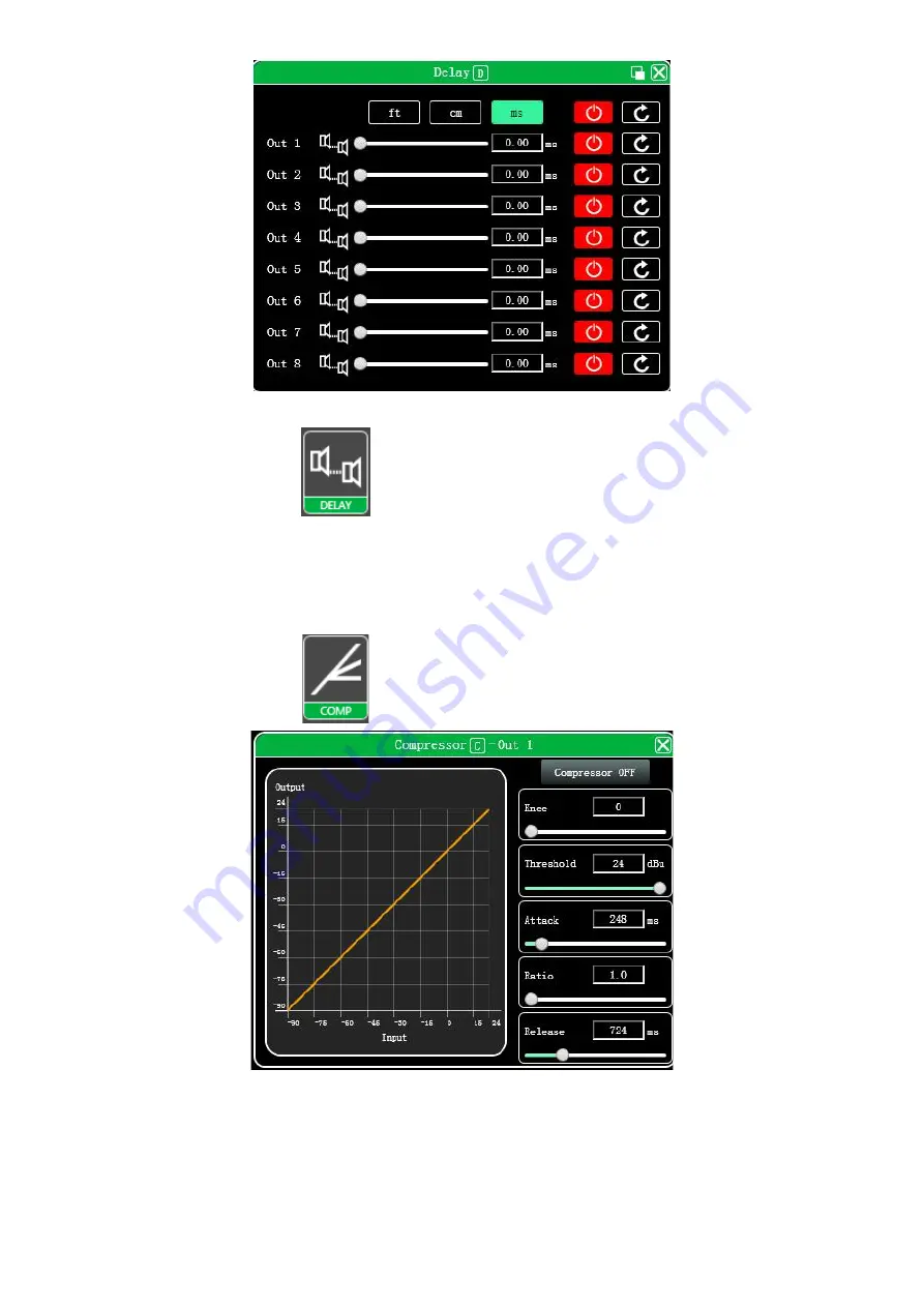
Figure 7.10 Output delay setting module 

Double- click in the function button 

, and the output delay function interface shown in Figure 7.10 will pop up. 

The function and operation method are the same as input delay. 


7.11 Output compressor 

Double- click in the function button 

, the following Figure 7.11 output compressor function interface pops up. 


7.11 Output compressor function interface 


7.12 Output limiter 

Summary of Contents for i3600

Page 1: ...Page 1 34 Professional Audio Processor i4800 i3600 User Manual...

Page 2: ...7 Function Interface Introduction 16 7 1 Main interface of input function 16 7 2 Test signal function 16 7 3 Input noise gate 17 7 4 Input Parametric Equalizer PEQ 18 7 5 Dynamic EQ 20 7 6 Input delay...

Page 3: ...nal performance Auditorium Multi functional hall Conference system Chapter 2 Technical Parameters 2 1 Features i3600 provides with 3 input channels and 6 output channels i4800 provides with 4 input ch...

Page 4: ...ise floor 20Hz 20kHz A wt 93dBu THD N 90dB 0dBu 1kHz A wt Line SNR 108dB 16dBu 1kHz A wt Line COMMUNITICATION PORTS AND INDICATORS USB Micro B type free drive RS232 Serial port communication TCP IP ne...

Page 5: ...NPUT EDIT MUTE LIGHT LIMIT STATUS LIGHT 0dBu INPUT LEVELLIGHT 24dBu INPUT LEVELLIGHT OUTPUT EDIT MUTE LIGHT INPUT LONG PRESS EDIT INPUT SHORT PRESS MUTE OUTPUT LONG PRESS EDIT OUTPUT SHORT PRESS MUTE...

Page 6: ...ENU Menu key Enter the main menu use BACK and NEXT keys to select different sub menus ENTER Enter key Enter submenu or function to edit parameters confirm selection change parameters BYPASS Bypass key...

Page 7: ...nes It can store the configuration parameters of the machine in the machine and the computer providing a very convenient way to preset scenes and parameters for different systems The software has high...

Page 8: ...tware does not include the Microsoft NET Framework 4 0 runtime If necessary please download and install it from the official Microsoft website 5 3 Software operating Steps Double click the executable...

Page 9: ...Figure 6 1 the module corresponding to the red word in the main interface of the function each module is as follows 1 Menu bar 2 Scan button 3 Setting button 4 Joint debugging button 5 Equipment list...

Page 10: ...ter disk 4 Save save the current equipment management project in the computer disk 5 Save as save the current equipment management project to the computer disk Device Figure 6 1 2 Device menu As shown...

Page 11: ...onnected devices in the device list Preset Figure 6 1 4 Device Preset menu As shown in Figure 6 1 4 device preset menu Save select the saved gear save all the parameters of the current automatic gear...

Page 12: ...m menu Language multi language switching supports simplified traditional and ENGLISH About the current host computer software and device firmware version information Upgrade call the upgrade applet to...

Page 13: ...group in the middle frame and then select the synchronization settings required After pressing the OK button the grouping is successful You can also use the same operation to modify the network group...

Page 14: ...ify the computer IP address to ensure that the IP of the device and the computer are in the same network segment 6 1 7 Function control keys Open or close the related function interface and positionin...

Page 15: ...mode channelname and other information of each channel controlthe corresponding channel gain DSP function master switch and turn on the input and output channel grouping joint adjustment function to a...

Page 16: ...can be operated in the input mode analog input digital input and test signal can be selected from one of three and a channel can only have one input mode In this software only products with D4 displa...

Page 17: ...is selected as an analog signal it will switch back to analog signal input and turn off the test signal 7 3 Input noise gate Double click in the function button the following Figure 7 3 input noise ga...

Page 18: ...nce control points Bypass turn on or off all equalizer EQ of the current channel at the same time Preset save all the setting parameters of the equalizer of the current channel to the computer and rec...

Page 19: ...ontrol point and press and hold the right mouse button to adjust the Q value 7 4 4 EQ control parts As shown in Figure 7 4 above below the curve chart all the EQ control serial numbers and correspondi...

Page 20: ...ll delete and rename functions of the equalizer setting parameters The preset parameters are saved to the computer in the designated folder in the software 7 5 Dynamic EQ Double click in the module bu...

Page 21: ...alue 7 6 Input delay Double click in the module button the following figure 7 6 input delay function interface will pop up Figure 7 6 Input delay setting module As shown above the delay lists all inpu...

Page 22: ...ay Name current name of FIR preset file Channels select click and show current channel with FIR curve support multiple channels Parameters select Design design switch button for interface Magnitude sh...

Page 23: ...alue is the input and output channel mixing key When the mixing key is green double click the value box to switch the state the input channel and output channel signal realizes the mixing function The...

Page 24: ...operation mode are the same as input equalizer But the output has increased the high and low pass filter function than the input as described below 7 9 1 EQ high and low pass filter As shown above hi...

Page 25: ...function interface shown in Figure 7 10 will pop up The function and operation method are the same as input delay 7 11 Output compressor Double click in the function button the following Figure 7 11...

Page 26: ...up Figure 7 12 Output limiter setting module 7 13 Output module Double click in the module button and the output setting module shown in Figure 7 13 will pop up Figure 7 13 Output setting module As s...

Page 27: ...els link interface will pop up as following Figure 13 1 Figure 7 15 Channels link interface As shown in the figure above the three lists from left to right are divided into channel list group list and...

Page 28: ...t for management is the factory name the user cannot modify it if the connection method is TCP the factory name will be left after the connection is connected The side will display the IP address of t...

Page 29: ...ree parts as follows Software information display the current device s upper and lower computer version number and date information Device information display the current device name and device groupi...

Page 30: ...numbers 7 20 Channels copy Click Device Channels Copy in the menu bar of the main software interface and the following Figure 7 20 Channels Copy interface will pop up Figure 7 20 Channel Copy interfa...

Page 31: ...rresponding selected preset Recall Recall the selected preset to the current parameters of the device Delete delete the selected preset parameter Clear Clear all preset parameter records that are not...

Page 32: ...u can open the firmware upgrade interface as shown in the figure above After selecting the corresponding upgrade file in the Upgrade File column click UPGRADE in the upper right corner and the system...

Page 33: ...nits to realize the interconnection and intercommunication of digital signals between devices and have a stable and reliable signal synchronization function Dante system construction Dante Controller...

Page 34: ...Dante will memorize its own routing configuration After turning off the power and restarting Dante routing will restore itself There is no need to configure the computer again At this time the Dante...

Reviews: