


RAD-900-...
PHOENIX CONTACT
3827_en_B
2.1.1
Structure
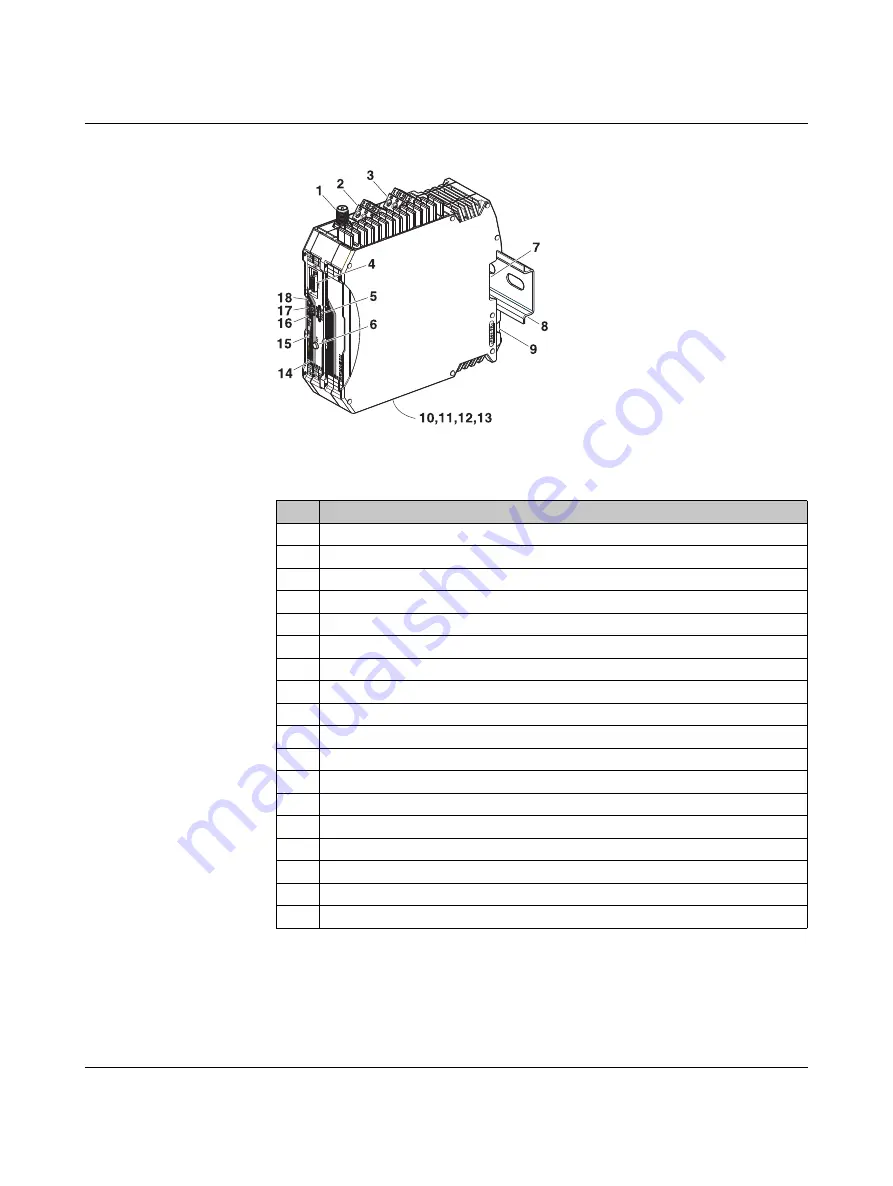
Figure 2-1
RAD-900-IFS structure
Table 2-1
RAD-900-IFS structure
Item
Designation
1
RSMA antenna connection (socket)
2
Test output RSSI (0...3 V DC) for evaluation of the wireless signal strength
3
Device supply (+24
V
DC, 0
V)
4
12-pos. programming interface (S-PORT)
5
RAD ID address setting via thumbwheel
6
SET button
7
Connection option for TBUS DIN rail connector
8
DIN rail
9
DIN rail release latch
10
Connection terminal block RS-485 interface
11
Connection terminal block RS-232 interface
12
Relay output with PDT contact (floating)
13
D-SUB 9 connector (RS-232 interface)
14
RS-232/485 serial interface status LED (RX/TX)
15
LED bar graph for displaying the wireless signal strength
16
ERR status LED, red (communication error)
17
DAT status LED, green (BUS communication)
18
PWR status LED, green (supply voltage)