background image

AXC 3050

20

PHOENIX CONTACT

8686_en_01

2.5

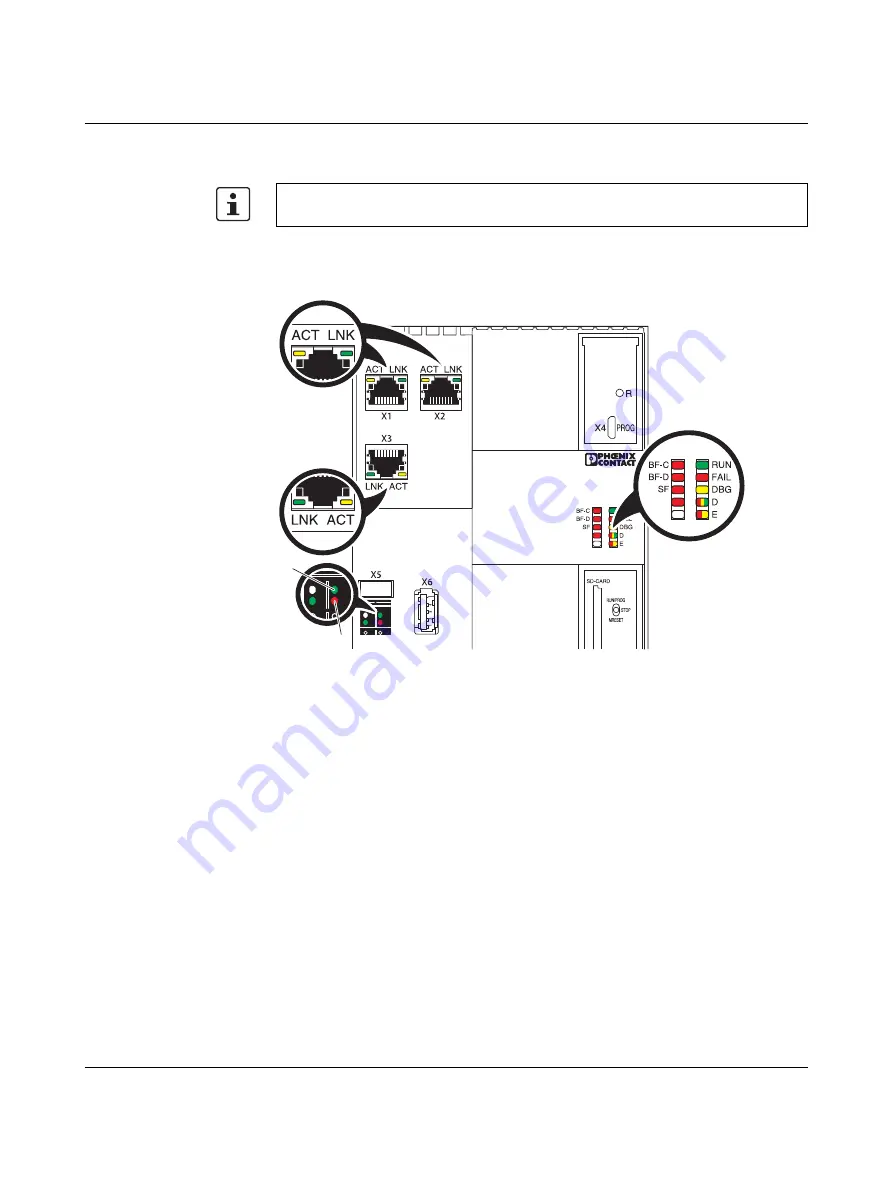
Diagnostics and status indicators

The diagnostics and status indicators are used for quick local error diagnostics.

Figure 2-7

Diagnostics and status indicators

The descriptions for diagnostics and status indicators apply to all controllers for Axioline F 

listed on the inner cover page of this user manual.

UL

BOOT

PN/AXC/PLC

BOOT

ETH

ETH

UL

PWR

1

2

8686A020

Summary of Contents for AXC 3050

Page 1: ...User manual Installation and operation of the AXC 3050 controller UM EN AXC 3050...

Page 2: ..._01 Installation and operation of the AXC 3050 controller UM EN AXC 3050 01 Designation Version or later HW Version or later FW Order No AXC 3050 01 5 50 2700989 User manual Designation Revision Order...

Page 3: ...oenixcontact com Published by PHOENIX CONTACT GmbH Co KG Flachsmarktstra e 8 32825 Blomberg GERMANY Should you have any suggestions or recommendations for improvement of the contents and layout of our...

Page 4: ...ducts in your specific application in particular with regard to observ ing the applicable standards and regulations All information made available in the technical data is supplied without any accompa...

Page 5: ...switch 24 2 7 Reset button concealed 26 2 8 Parameterization memory 26 2 9 Internal basic circuit diagram 28 2 10 Interfaces 29 2 10 1 Communication paths 29 2 10 2 USB interface USB A 32 2 11 Connec...

Page 6: ...communication 85 4 15 Function blocks for the fast counters function 86 4 15 1 Counter operating modes 90 4 16 Function blocks for Axioline acyclic PDI communication 93 5 Useful information on AXC 305...

Page 7: ...13 System time 119 6 14 Ethernet interfaces 119 6 15 Fast counters 120 7 Web based management WBM 121 7 1 Requirements for the use of WBM 121 7 2 Selecting the language 121 7 3 Functions information...

Page 8: ...AXC 3050 8 PHOENIX CONTACT 8686_en_01...

Page 9: ...on Ordering data on page 131 Connecting cable optional For the ordering data for a corresponding USB cable see Section Ordering data on page 131 PC Worx automation software Version 6 30 part of the AU...

Page 10: ...AXC 3050 10 PHOENIX CONTACT 8686_en_01...

Page 11: ...via the network Ether net The powerful processor can be programmed in all five IEC 61131 programming lan guages and ensures quick control task processing Integrated Ethernet con nection The integrated...

Page 12: ...line F system please refer to the online help for the PC Worx software and the Axioline F System and installation UM EN AXL F SYS INST and Axioline F Diagnostic registers and error messages UM EN AXL...

Page 13: ...a plug in parameterization memory in the form of an SD memory card referred to as SD card below and or a USB memory stick referred to as USB stick below The plug in parameterization memory is optional...

Page 14: ...an be queried using system variables see Section Power storage realtime clock on page 118 2 2 Possible fields of application of the AXC 3050 2 2 1 The AXC 3050 as a distributed controller of an Axioli...

Page 15: ...r Key A PROFINET controller in the example AXC 3050 as the head of an Axioline F station B PROFINET device in the example PROFINET BK module with connected Axioline F I O modules PROFINET controller i...

Page 16: ...a lower level PROFI NET ring network which has been designed redundantly using the Media Redundancy Pro tocol MRP In the example the AXC 3050 controller operates as an IO device with control function...

Page 17: ...T DISPLAY RFC 460R PN 3TX Ord No 2700784 LNK LNK LNK USB SYNC ACT ACT ACT LAN1 1 LAN1 2 LAN2 24VDC C 00 A0 45 06 04 02 MAC Address 1 2 3 4 LINK Mode US2 FAIL X9 US1 GND US2 GND X10 R1 R2 FL SWITCH SMS...

Page 18: ...ore unpacking the controller NOTE Electrostatic discharge The AXC 3050 contains components that can be damaged or destroyed by electrostatic discharge When handling the controller observe the necessar...

Page 19: ...ming interface 4 Electronics module 5 Ethernet interfaces X1 X2 X3 6 FE tab X5 2 8 mm for optional connection to functional earth ground 7 Connector for connecting the supply voltage 8 USB interface X...

Page 20: ...tus indicators are used for quick local error diagnostics Figure 2 7 Diagnostics and status indicators The descriptions for diagnostics and status indicators apply to all controllers for Axioline F li...

Page 21: ...no full duplex operation at Ethernet port which has been assigned the PROFINET device function X1 X2 or X3 Flashing 1 Hz Link status available no communication connection to the PROFINET controller Th...

Page 22: ...ess Off Device firmware running AXC Axioline diagnostics D Red yel low green Axioline diagnos tics Red on Bus error Axioline F local bus Yellow ON READY Device is ready for operation no data is exchan...

Page 23: ...reen Link status Off Connection not established successfully On Connection established successfully link the controller is able to contact another network device ACT gelb Activity status Off Data tran...

Page 24: ...the option of triggering a firmware update Read fur ther details in Section Mode selector switch triggers update via USB stick or SD card on page 133 8686A003 Table 2 2 Controller operating modes Oper...

Page 25: ...hree seconds STOP position until the RUN and FAIL LEDS flash simultaneously with 0 5 Hz Set the switch to the MRESET position for three to five seconds un til the FAIL LED flashes with 0 5 Hz Release...

Page 26: ...pplication program and the retain data are not deleted Approximately 3 13 s until the BOOT LED starts to flash The controller is restored to default settings delivery state The IP address settings the...

Page 27: ...ending on its usage the card must be inserted prior to switch on in order for it to be used by the controller It is therefore essential that you observe the information in Section Operating the contro...

Page 28: ...NK ACT RJ45 Ethernet Microprocessor Transmitter Chipset LED PROG service programming interface USB interface USB A Reset button RTC RJ45 interface Power supply unit Functional earth ground connection...

Page 29: ...s 1 Ethernet 2 USB Key 1 3 x Ethernet X1 X2 X3 RJ45 sockets 10 100 BASE T X X1 X2 or X3 PROFINET device interface optional X3 PROFINET controller interface 2 1 x USB X4 Micro USB B socket You can conn...

Page 30: ...igure 2 13 Ethernet interface and pin assignment Figure 2 14 Connecting the Ethernet cable to the controller Use an Ethernet cable according at least to CAT5 of IEEE 802 3 Observe the bending radii of...

Page 31: ...Figure 2 15 Connecting cable between PC and AXC 3050 In order to use the X4 USB interface of the AXC 3050 the Phoenix Contact USB RNDIS Driver V1 00 xyy exe driver must be installed yy 32 64 depending...

Page 32: ...ry SD card USB stick on page 99 Section Copy Update function via plug in parameterization memory USB stick on page 104 Section Updating the AXC 3050 firmware on page 133 2 11 Connection for the supply...

Page 33: ...hrough the Axioline F station local bus A bus base module is supplied with the controller Figure 2 18 Structure of the bus base module 1 Bus base module 2 Connection of the local bus to the controller...

Page 34: ...AXC 3050 34 PHOENIX CONTACT 8686_en_01...

Page 35: ...of the controller there are four FE springs that make contact with the DIN rail when the controller is placed on the DIN rail When using the controller for the first time protect the Axioline F system...

Page 36: ...onnection via the FE tab is only to be used to safely discharge in terference in particularly harsh environments where the DIN rail may be contaminated and the normal FE contacts no longer function co...

Page 37: ...e ambient temperatures and any other special features e g derating specified in the device module specific documentation for the devices modules installed in the Axioline F station The controller must...

Page 38: ...side automatically creates potential and bus signal connections between the individual station components 3 3 Mounting the controller To mount the controller proceed as follows Disconnect the power to...

Page 39: ...n the controller Place the controller vertically on the first bus base module and the DIN rail until it snaps into place with a click Make sure that the device plug for the bus base connection is situ...

Page 40: ...errule if required Solid cable ferrule Insert the cable in the terminal point It is clamped automatically Figure 3 6 Connecting a solid cable Stranded cable Open the spring by pressing on the spring l...

Page 41: ...3 4 Removing the controller Proceed as follows to remove the controller from the DIN rail Disconnect the power to the station Removing the cable The cables should only ever be removed from the supply...

Page 42: ...45 plug for the Ethernet connection by pressing on the snap in lug and remove the plug Removing the controller Insert a suitable tool e g bladed screwdriver into the upper and lower snap on mech anism...

Page 43: ...tion etc is stored on the SD card When the SD card is inserted in the new controller this data is immediately available after the controller initialization phase For additional information on operatin...

Page 44: ...supply units from Phoenix Contact that can be used please re fer to Section Accessories on page 132 Figure 3 12 Overload rangewithfall back characteristic curve Figure 3 13 Overload range without fall...

Page 45: ...es The DBG and BOOT LEDs go out after approximately another 30 s The DBG and BOOT LEDs go out after approximately another 5 s The D LED is permanently illuminated in yellow The D LED starts to light u...

Page 46: ...Applying light pressure push the parameterization memory into the slot in the direction shown in Figure 3 14 B until the snap on mechanism releases the parameterization memory and partially ejects it...

Page 47: ...of the AUTOMA TIONWORX Software Suite 1 81 AddOn V3 4 3 Start Creating a new project Before applying the settings described below create a new project in PC Worx In the New Project dialog box select...

Page 48: ...ample project see Figure 4 7 on page 55 proceed as follows In the Windows Control Panel check the settings for your PC network adapter If necessary adjust these settings so that the AXC 3050 can be ac...

Page 49: ...he assigned IP address in the network via this interface provided the function in PC Worx has been enabled An IP address must be assigned to the interfaces X1 X2 or X3 if you wish to operate AXC 3050...

Page 50: ...to in stall the USB driver see Section 4 1 on page 47 No other settings are required Switch to the bus configuration workspace Select the controller node in the example AXC 3050 Select the Extended Se...

Page 51: ...ess to each interface Making settings Select the interface A in the example in Figure 4 2 LAN1 X1 In the Network Settings area enter the required IP address and subnet mask accord ing to Table 4 3 on...

Page 52: ...sful Transferring settings to the controller In order for the transferred network settings to take effect in the controller the AXC 3050 must be restarted In the Activate Network Settings area click o...

Page 53: ...status window Figure 4 5 Activate Network Settings Service executed successfully The network settings assigned to the AXC 3050 are active Testing network settings You can test whether the settings ar...

Page 54: ...the AXC 3050 successfully PC Worx sends a cor responding acknowledgment message Assigning IP settings To set the IP addresses in PC Worx proceed as described below Switch to the bus configuration wor...

Page 55: ...of the controller to which you wish to assign the IP address settings Ethernet interface X3 in the example 1 8686A021 Running BootP connecting Ethernet interfaces individually Assignment via BootP ca...

Page 56: ...orm a cold restart for the controller To do this switch the supply voltage off and then on again after about two seconds The controller is assigned the IP address which is specified in the project for...

Page 57: ...rk settings Figure 4 6 on page 53 4 5 Read Axioline PC Worx offers a convenient option for transferring the Axioline modules connected to the controller to the project and adapting them according to y...

Page 58: ...en configured are also read in again The previously configured bus configuration is overwritten Figure 4 12 Read Axioline Axioline modules that have not yet been read in Figure 4 13 Read Axioline Axio...

Page 59: ...iguration and are displayed in the Bus Structure window The device details for a device can be displayed by selecting it Figure 4 16 Read in Axioline devices For instructions on how to proceed with pr...

Page 60: ...interface and to name the read PROFINET devices if necessary proceed as described in this example 4 6 1 Reading the PROFINET network In the Bus Structure window select Read PROFINET in the PROFINET c...

Page 61: ...4 18 Read PROFINET dialog box Select the Axioline PROFINET AXL F BK PN BK module and insert it as a PROFINET device by clicking on the Insert A in Figure 4 18 button If the following Select PROFINET...

Page 62: ...se button to close the Read PROFINET dialog box A in Figure 4 18 on page 61 The PROFINET device inserted earlier will be displayed in the Bus Structure window refer to Figure 4 20 Device details are d...

Page 63: ...ice details in the Device parameters tab Figure 4 21 PROFINET devices device parameters PROFINET Axioline Stationname IP address In the PROFINET Stationnames tab you can assign a PROFINET name and its...

Page 64: ...IP address Click on the Assign IP button D in Figure 4 22 to assign the IP address displayed in the Bus structure window for the selected device refer to Figure 4 20 on page 62 PC Worx displays the f...

Page 65: ...n be planned depending on your application Activating the PROFINET IO device func tion of the AXC 3050 Enabling disabling the PROFINET device function of the AXC 3050 is via PC Worx To this end there...

Page 66: ...to Figure 4 25 on page 65 Successful execution of the service will be displayed in the status window see Figure 4 26 on page 66 To activate the above settings on the AXC 3050 the controller must be r...

Page 67: ...project is created in PC Worx The PROFINET controller is configured according to the application Bus structure in PC Worx device catalog Alternatively you can also create the PC Worx project by selec...

Page 68: ...ert it as a PROFINET device by clicking on the Insert but ton If the following Select PROFINET device description dialog box opens select the de vice description that corresponds to the AXC 3050 Make...

Page 69: ...to close the Read PROFINET dialog box The PROFINET device inserted earlier will be displayed in the Bus Structure window Figure 4 30 AXC 3050 inserted as a PROFINET device The process data of the PRO...

Page 70: ...have been performed How to proceed 1 Compile the PC Worx project by selecting the Rebuild Project item in the Code menu 2 Open the Project Control Dialog by clicking on the corresponding button once t...

Page 71: ...ath and Axioline Modules is set as the device type in the Device Representation area In this example the Slot Number and Order Designation are selected for the display of the Axioline modules Click on...

Page 72: ...of the Diag dialog box select Axioline Diagnostic as the view Figure 4 35 Diagnostic view selecting Axioline Diagnostic Diag then switches to diagnostic view of the connected Axioline system configure...

Page 73: ...AXC 3050 controller under PC Worx 8686_en_01 PHOENIX CONTACT 73 The following dialog box shows an Axioline module that is operating without errors Figure 4 37 Axioline module AXL F DI 16 1 HS 1H No er...

Page 74: ...that occur are diagnosed by Diag and displayed In the following example the supply voltage for the AXL F DI 16 1 HS 1H Axioline module is not present Diag shows the following Figure 4 38 Axioline mod...

Page 75: ...under PC Worx 8686_en_01 PHOENIX CONTACT 75 When the controller is selected the error is displayed as follows Figure 4 39 AXC 3050 controller Peripheral error Diagnostics can be used to identify erro...

Page 76: ...ng of the process data The local bus is then in the ACTIVE state The LED flashes green Start bus If a valid configuration frame has been generated the local bus can be started using this menu item The...

Page 77: ...r the controller in PC Worx 4 10 Download changes The Download Changes function supports the AXC 3050 as of the specified device ver sion in conjunction with the specified versions of the PC Worx soft...

Page 78: ...lder on Device The FTP functionality must be activated in Internet Explorer See Section Internet Explor er FTP functionality on page 80 User administration limiting access to the parameterization memo...

Page 79: ...ayed refresh the display after every action by means of the View Refresh com mand Figure 4 42 Internet Explorer file and folder structure of the parameterization memory In order to read or save the fi...

Page 80: ...PHOENIX CONTACT 8686_en_01 4 11 1 Internet Explorer FTP functionality Activate this setting in Internet Explorer under Tools Internet Options Advanced Figure 4 44 Internet Options Enable folder view f...

Page 81: ...e CPU_Set_Value_Request service Figure 4 45 Deactivating the FTP server 4 11 3 Activating deactivating the HTTP server To protect the controller against unauthorized access it may be necessary to deac...

Page 82: ...ed in PC Worx for the AXC 3050 which is started in the case of the voltage failure event To do this proceed as follows Switch to the IEC programming workspace In the context menu for the Tasks node se...

Page 83: ...Confirm your entries with OK The previously defined PowerOf event task is displayed in the Project Tree Window Figure 4 49 PowerOf event task PC Worx Missing program instance error message If PC Worx...

Page 84: ...d modifications made locally via function blocks or firmware services can be detected The functional blocks are valid for All file operations are subject to the following restrictions No directory hie...

Page 85: ...ble below in the specified hard ware firmware versions and support the specified maximum number of TCP IP or UDP com munication connections Order designation Blocks As of hardware version HW As of fir...

Page 86: ...ing process Alternatively presets can be defined by the level at the assigned inputs of the Axioline I O module s In this case the appropriate counter mode must be specified at the MODE input of the f...

Page 87: ...put refer to Section 4 15 1 on Page 90 EDGE BYTE This value determines upon which edges on the counter input should be counted 0x00 counting on positive edge 0x01 counting on negative edge 0x02 counti...

Page 88: ...7 Inputs of the CNT1 and CNT2 function blocks Name Data type Description An event task assigned to the CNTx counter is triggered as follows Upon reaching the value determined for the EVENT_VALUE inpu...

Page 89: ...is saved As soon as the controller returns to the RUN state the counting process is con tinued based on the saved counter status Table 4 9 Status values of the STATUS output ERROR TRUE Value Status 0...

Page 90: ...k the pre sets for the counting direction and start of the counting process are defined by the level at the assigned inputs of the Axioline I O modules In this case the corresponding inputs at the DIR...

Page 91: ...c tion and counting process enable The signal at the RESET input of the function block is ORed to the signal of the assigned Axioline I O module input for internal processing Table 4 10 Counter operat...

Page 92: ...ignal is present on the assigned input Reset Reset of the counter status The current counter status CV is set to zero If a TRUE signal is present on the assigned input or If a positive edge is detecte...

Page 93: ...ation e g for an RS 232 special function module where the communication data is not exchanged between the controller and Axioline F module via process data but by means of objects via PDI Because PDI...

Page 94: ...AXC 3050 94 PHOENIX CONTACT 8686_en_01...

Page 95: ...word using the firmware service CPU_Set_Value_Request By default upon delivery the user name is Anonymous and the password is no password This setting is also restored if the AXC 3050 is reset to its...

Page 96: ...of the parameterization memory Password access to Inter net Explorer Open Internet Explorer by clicking on the Open FTP Folder on Device button in the device details in the Extended Settings tab Enter...

Page 97: ...entry Figure 5 4 User name and password The content of the parameterization memory is then displayed in Internet Explorer Figure 5 5 Content of the parameterization memory As the web browser does not...

Page 98: ...uding the user name and password and confirm your entry by pressing Return Figure 5 7 Entering the FTP address including the user name and password Alternatively you can just enter the user name ftp U...

Page 99: ...ange operation without SD card operation with SD card To change the controller mode from operation without SD card to operation with SD card proceed as follows Switch off the supply voltage of the con...

Page 100: ...ith the SD card there is no data available on the internal parameterization memory The controller therefore does not have an IP address When switching on the controller it automatically sends a Boot_R...

Page 101: ...data includes Application specific data which is saved in the CF ROOT folder comprises for example the application program PC Worx project boot project the visualiza tion program web visualization and...

Page 102: ...ettings to the READY operating state and uses the internal parameteriza tion memory The IP address settings have not been pa rameterized As a minimum you need to assign the X3 IP address set tings to...

Page 103: ...D card as main memory SD card SD card inserted Application and device specific data device settings can be found on the SD card which is used as the main mem ory parameterization memory and or are sav...

Page 104: ...er it to other suitable controllers in the application via USB stick All that is then necessary is to make the device specific settings for each controller IP address settings PROFINET device names DN...

Page 105: ...sing the mode selector switch Key For the exact procedure on actuating the mode selector switch please refer to Section Updating the AXC 3050 firmware on page 133 A Read Read the current status set in...

Page 106: ...he firm ware update is started and or the CFROOT folder is copied to the active parameterization memory internally or inserted SD card once the mode selector switch is actuated The update is performed...

Page 107: ...isplay these directo ries for example if you access the controller via FTP refer to Section Parameterization memory and Internet Explorer on page 78 For the inserted SD card the SDDisk direc tory is d...

Page 108: ...ccess with the same mechanisms as the internal memory In this regard no differences should be noted by the user In order to access an inserted SD card which is used as an additional memory or a USB st...

Page 109: ...Useful information on AXC 3050 8686_en_01 PHOENIX CONTACT 109 Figure 5 13 FILE function blocks in PC Worx...

Page 110: ...AXC 3050 110 PHOENIX CONTACT 8686_en_01...

Page 111: ...ecific Axioline F local bus state is assigned to each bit in the diagnostic sta tus register The following system variables can be used to read the diagnostic status register informa tion The followin...

Page 112: ...nother The diagnostic parameter register is rewritten whenever an error occurs If no interference has been detected the diagnostic parameter register contains the value 0 Special case if an interface...

Page 113: ...es PNIO_DIAG_AVAILABLE BOOL Diagnostics available At least one PROFINET device is indicating a diagnostic alarm for an active connection The corresponding device s can be identified using the RALRM di...

Page 114: ...enix Contact Table 6 3 PROFINET system variables PROFINET controller functionality System variable Type Meaning Table 6 4 PROFINET system variables PROFINET device function System variable Type Meanin...

Page 115: ...56 OUT process data Memory area for OUT process data that the PROFINET device sends to the higher level controller higher level PROFINET controller PND_S1_INPUTS PND_IO_256 IN process data Memory area...

Page 116: ...ogram PLCDEBUG_FORCE BOOL Variable s forced At least one variable is being continuously overwritten forced PLCDEBUG_POWERFLOW BOOL Address status switched on enabled PLC_TICKS_PER_SEC INT System ticks...

Page 117: ...Runtime system RUN COP_DIAG_STATUS_REG_FC_STOP BOOL Runtime system STOP COP_DIAG_STATUS_REG_FC_HALT BOOL Runtime system HALT COP_DIAG_STATUS_REG_FC_LDG BOOL Runtime system LOADING COP_DIAG_STATUS_REG_...

Page 118: ...les of the power storage and realtime clock System variable Type Meaning RTC_BATTERY_LOW BOOL Low capacity of the power storage for the realtime clock RTC_DATA_INVALID BOOL Realtime clock data is inva...

Page 119: ...tem time seconds RTC_DAY INT System time day RTC_MONTH INT System time month RTC_YEAR INT System time year Table 6 15 System variables of the Ethernet interfaces System variable Type Meaning LAN_PORT1...

Page 120: ...nputs assigned to the Axioline I O modules in PC Worx in the Fast I O coupling tab Table 6 16 System variables for the fast counters function System variable Type Meaning CNT1_F1 BOOL Function block C...

Page 121: ...M WBM via Ethernet As the web server operates using the Hyper Text Transfer Protocol a standard browser can be used Access is via the URL http IP address of the device Example http 192 168 0 2 You can...

Page 122: ...e following areas Information general device information Diagnostics device specific diagnostics 7 3 1 Web page information Web page general data Here you will find general details for the device e g...

Page 123: ...gement WBM 8686_en_01 PHOENIX CONTACT 123 Web page technical data Here you will find technical details on the device e g on the ambient conditions device memory and supply voltage Figure 7 3 Web page...

Page 124: ...AXC 3050 124 PHOENIX CONTACT 8686_en_01 Web page diagnostics indicators This page describes the meaning of the diagnostics indicators LEDs Figure 7 4 Web page diagnostics indicators...

Page 125: ...8686_en_01 PHOENIX CONTACT 125 7 3 2 Web page diagnostics Web page controller Here you will find a brief description of the LED indicators which are displayed during the runtime of the device Figure...

Page 126: ...immediately once the IP ad dress is entered in the browser The Web based management can be reached by entering IP address webui To switch from Web based management to the WebVisit visualization click...

Page 127: ...enix Contact see Ordering data on page 131 100 74 122 4 125 9 8686A013 General data Color Traffic gray A RAL 7042 Weight Approx 380 g Mounting type DIN rail Realtime clock Yes System limits of the con...

Page 128: ...at UL Typ 9 8 W without I Os Max 23 5 W with 2 A load at UBus for the I Os Functional earth grounding Logic GND and functional earth ground FE are permanently connected in the housing Protective meas...

Page 129: ...ethod USB type A Counter input Number of inputs Max 2 via any digital inputs of the AxiolineAxioline F modules Input frequency Max 100 kHz with module AXL F DI16 1 HS 1H Supported protocols Supported...

Page 130: ...1 s day at 25 C Power reserve Typ 10 days the buffer time of the clock depends on the ambient tempera ture of the controller If the AXC 3050 is not supplied with voltage for longer than this time we r...

Page 131: ...nes 2 kV Surge voltage EN 61000 4 5 IEC 61000 4 5 Criterion B DC supply lines 0 5 kV 0 5 kV symmetri cal asymmetrical Conducted interference EN 61000 4 6 IEC 61000 4 6 Criterion A Test voltage 10 V No...

Page 132: ...am and configuration memory plug in 2 GB with license key for func tion block libraries e g for SNMP SQL wireless motion functions etc SD FLASH 2GB APPLIC A 2701190 1 USB memory stick IP20 USB 2 0 VS...

Page 133: ...emory on page 26 To update the firmware please proceed as described in the AH EN FIRMWARE UP DATE ILC 1 3 RFC 4 application note It can be downloaded at phoenixcon tact net products If the firmware up...

Page 134: ...n for one to two seconds Following the switching operation the RUN and DBG LEDs light up flash 4 Once the DBG LED has gone out release for a maximum of two seconds STOP posi tion and then press and ho...

Page 135: ...are update The RUN FAIL and DBG LEDs flash according to Figure A 1 with 0 5 Hz The BOOT LED flashes during the initialization t2 Firmware update The RUN and DBG LEDs flash alternately during the firmw...

Page 136: ...AXC 3050 136 PHOENIX CONTACT 8686_en_01...

Page 137: ...1 Internal basic circuit diagram AXC 3050 28 Figure 2 12 Communication paths 1 Ethernet 2 USB 29 Figure 2 13 Ethernet interface and pin assignment 30 Figure 2 14 Connecting the Ethernet cable to the c...

Page 138: ...Axioline Axioline modules that have not yet been read in 58 Figure 4 13 Read Axioline Axioline modules that have already been configured 58 Figure 4 14 Read Axioline Re insert all modules 58 Figure 4...

Page 139: ...server 81 Figure 4 46 Insert task context menu 82 Figure 4 47 Inserting task dialog box 82 Figure 4 48 Task settings for PowerOf dialog box 83 Figure 4 49 PowerOf event task 83 Figure 4 50 CNTx funct...

Page 140: ...on blocks in PC Worx 109 Section 7 Figure 7 1 WBM user interface selecting the language 121 Figure 7 2 Web page general data 122 Figure 7 3 Web page technical data 123 Figure 7 4 Web page diagnostics...

Page 141: ...e CNT1 and CNT2 function blocks 88 Table 4 9 Status values of the STATUS output ERROR TRUE 89 Table 4 10 Counter operating modes 90 Table 4 11 Overview of the function blocks 93 Section 6 Table 6 1 Sy...

Page 142: ...le 6 13 System variables of internal device temperature monitoring 119 Table 6 14 System variables of the system time 119 Table 6 15 System variables of the Ethernet interfaces 119 Table 6 16 System v...

Page 143: ...sending it to the controller 70 M MAC address 43 Mode selector switch 19 24 Mounting 38 Mounting location 36 Mounting position 36 O Operating elements 19 P Parameterization memory 26 Parameterization...

Page 144: ...AXC 3050 144 PHOENIX CONTACT 8686_en_01 U Updating the firmware 133...

Page 145: ...Index 8686_en_01 PHOENIX CONTACT 145...

Page 146: ...AXC 3050 146 PHOENIX CONTACT 8686_en_01...

Reviews: