Phoenix Contact 2986229 User Manual Download Page 35

Hardware: PSR-TRISAFE-S safety module

103503_en_03

PHOENIX CONTACT

3-3

3.2

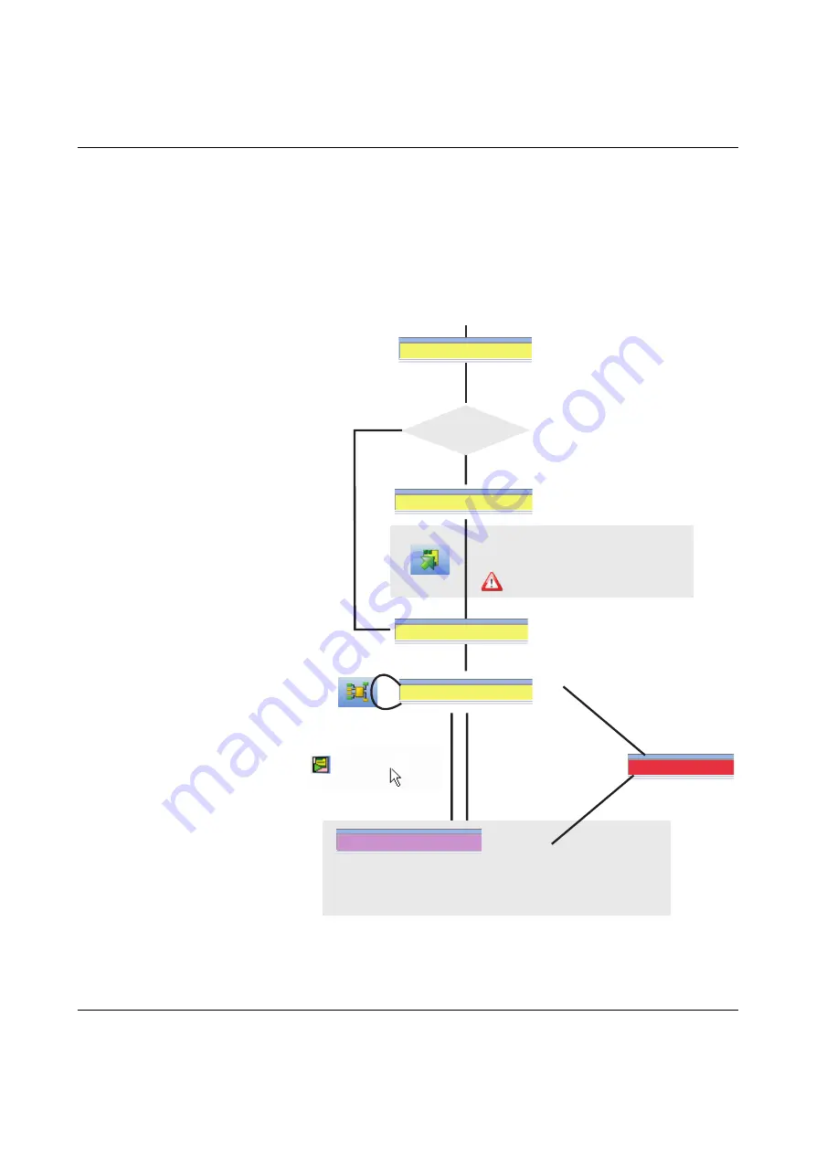
Operating modes (status) of PSR-TRISAFE-S

The diagram below illustrates the possible operating modes (status) of the PSR-TRISAFE-S 

safety module and the possible status transitions. When there is a USB connection to the 

PC, the module status is indicated on the far left in the status bar of the SAFECONF 

configuration software.

Figure 3-3

Diagram: Possible operating modes (status) for the PSR-TRISAFE-S safety 

module

Controller: Connected

Controller: Error

Safety module and PC 

are connected via USB, 

safety module 

is switched on

Download project 
Execution starts following
acknowledgment ("Confirm" button on the device)

Change between 
safe online mode
and standard
startup mode

Error during execution

Error during execution

Connection editor

 online or offline

USB connection (PC to safety module) must not be interrupted 
and project in SAFECONF must not be changed.
Otherwise safety module is stopped and 
changes to the safe state after 10 minutes.

Controller: No project

Controller: Startup

Startup

Controller: Timeout

Temporary state during: 
- Saving process (during download)
- Initialization 
- Safety module selftest

Yes

No

Temporary state during: 
- Communication establishment
- Initialization 
- Safety module selftest

Initial startup?

Controller: Timeout

Summary of Contents for 2986229

Page 1: ...INTERFACE UM EN PSR TRISAFE S Order No User Manual Device description configuration and startup of the PSR TRISAFE S safety module...

Page 2: ......

Page 3: ...for INTERFACE 103503_en_03 PHOENIX CONTACT 2011 06 22 Device description configuration and startup of the PSR TRISAFE S safety module UM EN PSR TRISAFE S 03 Designation Order No PSR TRISAFE S PSR SCP...

Page 4: ...Explanation of symbols used and signal words The following types of messages provide information about possible property damage and general information concerning proper operation and ease of use Thi...

Page 5: ...rors in the information cannot be ruled out Phoenix Contact does not offer any guarantees as to the reliability accuracy or completeness of the information All information made available in the techni...

Page 6: ...2000 Windows XP and Windows Vista are trademarks of the Microsoft Corporation All other product names used are trademarks of the respective organizations How to contact us Internet Up to date informa...

Page 7: ...System requirements for the SAFECONF configuration software 2 15 3 Hardware PSR TRISAFE S safety module 3 1 3 1 Device description 3 1 3 2 Operating modes status of PSR TRISAFE S 3 3 3 3 Operating an...

Page 8: ...up the project 4 18 4 5 5 Documenting the signal assignment and the project 4 19 4 6 Simulation mode in SAFECONF 4 21 5 Configuration and startup 5 1 5 1 Configuration overview from A to Z 5 1 5 2 Do...

Page 9: ...Please also read the Qualified personnel section in General safety notes on page 1 1 1 2 General safety notes Requirements Knowledge of the following is required The PSR TRISAFE S safety module used a...

Page 10: ...s errors within the safety equipment e g cross circuits Observe startup behavior Some of the safe functional blocks in the SAFECONF configuration software have parameters for specifying a startup inhi...

Page 11: ...ly use power supply units with safe isolation and PELV according to DIN EN 50178 VDE 0160 PELV This prevents short circuits between primary and secondary sides ESD DANGER Hazardous body currents or th...

Page 12: ...re and device parameterization Please note that you must carry out a validation every time you make a safety related modification to your overall system Use the relevant checklists when carrying out t...

Page 13: ...f electrical electronic programmable electronic safety related systems DIN EN ISO 13849 1 Safety of machinery Safety related parts of control systems best suited for less complex systems Part 1 Genera...

Page 14: ...ments and tests DIN EN 1088 Safety of machinery Interlocking devices associated with guards Principles for design and selection DIN EN 953 Safety of machinery Guards General requirements for the desig...

Page 15: ...the safe control system if they have been integrated into the execution process correctly and in such a way as to avoid errors The area of responsibility of the block manufacturer in terms of the fun...

Page 16: ...tion for I O devices e g sensors actuators etc connected to the PSR TRISAFE S safety module and connected to safe functional blocks in the safety logic SAFECONF configuration software In the online he...

Page 17: ...according to its configuration and controls the outputs accordingly The SAFECONF configuration software is used to configure the PSR TRISAFE S safety module and therefore provides the relevant editors...

Page 18: ...certain outputs In addition the software provides a safe parameter editor which can be used to configure each input and output of the PSR TRISAFE S safety module A special online mode supports a deta...

Page 19: ...with these modules is then established automatically via the connector on the PSR DIN rail connector Safety related cross wiring is not required see also Mounting the safety module on page 3 13 Figur...

Page 20: ...ng and checking electrosensitive protective equipment Mode selector switch evaluation of a mode selector switch and an enable switch Muting applications light grid monitoring with parallel muting Stop...

Page 21: ...triggered and following a return to normal operation for example after unlocking the emergency stop control device which means safe operation is possible again With an active startup restart inhibit t...

Page 22: ...which is also transmitted to O0 by the direct connection Table 2 1 Functional blocks that support a startup inhibit restart inhibit Functional block name Function Available inhibit EmergencyStop Emer...

Page 23: ...Implementing a startup inhibit restart inhibit and stop category 0 for safe output O0 K1 23 24 13 14 S1 S2 12 11 14 13 Reset 24V Not Halt E Stop EmergencyStop PSR TRISAFE S 103503a005 eps Wiring the...

Page 24: ...ircuit the same clock signal would be present at both inputs instead of two different ones Figure 2 4 Implementing cross circuit detection for an emergency stop control device at inputs I0 and I1 of t...

Page 25: ...agnostics in the event of a safe functional block error Wiring check Status indicators on the safety module Online tool tips in the connection editor Hardware diagnostics in the event of a safe functi...

Page 26: ...rder with the configuration software in online mode Therefore the LEDs for inputs I0 and I1 which are both directly connected to this functional block flash on the safety module Figure 2 6 Simplified...

Page 27: ...PSR TRISAFE S safety module must be running Switch the connection editor to online mode then to startup mode 2 In the connection editor position the cursor over the symbol for the input or output you...

Page 28: ...n of the error as a tool tip as soon as you position the cursor over the symbol for a functional block In the event of an error the tool tip contains not only a description of the error but also infor...

Page 29: ...gainst unauthorized modifications to the safety logic and the project information You can still open and display projects without a password but you can only change and save them once you have entered...

Page 30: ...se refer to the online help for SAFECONF Description Type Order No Pcs Pkt Configurable safety module Module with screw connections Module with spring cage connections PSR SCP 24DC TS S PSR SPP 24DC T...

Page 31: ...1 GB 2 GB Under Windows XP 2000 SP4 SP2 Minimum Recommended CPU 1 GHz x86 architecture 1 GHz x86 architecture Main memory 512 MB 1 GB All operating systems Minimum Recommended Hard disk 1 GB free mem...

Page 32: ...PSR TRISAFE S 2 16 PHOENIX CONTACT 103503_en_03...

Page 33: ...ts M0 to M3 which can be used for example to control a standard PLC or signaling units The two asynchronous test pulses at T0 and T1 provide safe cross circuit detection at the inputs of the safety mo...

Page 34: ...Figure 3 2 Block diagram for the PSR TRISAFE S safety module A1 A2 T0 24V 0V O0 O1 O2 O3 O0 O1 T0 T1 T1 I0 I1 I19 M0 M1 M2 M3 TBUS NON SAFE POWER 24V DC POWER 24V DC TEST PULSE MONITORING OUTPUT OUTP...

Page 35: ...nnected via USB safety module is switched on Download project Execution starts following acknowledgment Confirm button on the device Change between safe online mode and standard startup mode Error dur...

Page 36: ...to read the operating status of the safety module The following LEDs are available from left to right PWR Indicator for the power supply of the safety module DATA Indicator for communication with ext...

Page 37: ...edgment of a new IFS CONFSTICK program transmission via IFS CONFSTICK 1 7 Hz Extension unit replaced acknowledgment required Press the Confirm button on the device Normal operation without connected e...

Page 38: ...interface press and hold down the Confirm button while removing and inserting the IFS CONFSTICK using the specified procedure For the precise procedure please refer to Downloading the configuration u...

Page 39: ...al blocks and signals in the safety logic on page 4 11 Signal redundancy due to dual signals Every two adjacent signal inputs i e I0 and I1 I2 and I3 etc are grouped together and locked by default to...

Page 40: ...uld be present at both inputs instead of two different ones The SAFECONF configuration software specifies the clock signals to be used Cross circuit detection is implemented with test pulse T0 for eve...

Page 41: ...tion software specifies the clock signals to be used Cross circuit detection is implemented with test pulse T0 for even inputs I0 I2 I4 I18 For odd inputs I1 I3 I5 I19 test pulse T1 must be used for c...

Page 42: ...utput O0 and ground switching output O Figure 3 6 Example application for ground switching outputs O0 and O1 Ground switching output O0 can only be used in connection with output O0 ground switching o...

Page 43: ...tor 5 pos maximum cable length 3 m has been connected the appropriately configured PC detects the safety module automatically If the SAFECONF configuration software is already running the software det...

Page 44: ...If the IFS CONFSTICK is removed during operation the safety module sets all outputs to FALSE and indicates an error The safety module does not execute any more functions If the IFS CONFSTICK is remov...

Page 45: ...ipment and or serious personal injury Only qualified personnel may connect the power start up and operate this device According to the safety instructions in this documentation qualified personnel are...

Page 46: ...gether the required number of PSR DIN rail connectors for the connection station see Figure 3 9 A Snap this group of PSR DIN rail connectors onto the DIN rail see B and C Figure 3 9 Mounting PSR TBUS...

Page 47: ...e in direct contact with the sides of the housing All standard extension units must be mounted to the left of the PSR TRISAFE S safety module 7 End clamps should be mounted on both sides of the module...

Page 48: ...low 2 Supply voltage for the logic of the safety module and the alarm outputs at terminal block contacts A1 24 V and A2 0 V Once the supply voltage has been applied the PSR TRISAFE S safety module exe...

Page 49: ...3 12 Connection to screw terminal blocks left and spring cage terminal blocks right VORSICHT Ensure signal redundancy Ensure signal redundancy when connecting the signal lines of two channel control d...

Page 50: ...PSR TRISAFE S 3 18 PHOENIX CONTACT 103503_en_03...

Page 51: ...SAFECONF is installed you will be prompted to install the drivers for the safety module Follow the on screen instructions 5 In the Windows dialog box for driver installation select Install the softwar...

Page 52: ...nal in the connection editor and test the safety logic in this way Documentation checklist The configuration software provides a detailed project information dialog box where all information relating...

Page 53: ...nfiguration software 2 Toolbar Frequently used functions can be accessed quickly via the icons in the toolbar 3 Connection editor The connection editor is used to develop the safety logic by dragging...

Page 54: ...he message window can be used to track the progress of the project checking function When the check is started the message window opens automatically If the system detects an error when checking the p...

Page 55: ...functions The following safe functions are available in the SAFECONF toolbox and can be easily added to the safety logic using drag drop in alphabetical order AND Boolean ANDing EQ Boolean comparison...

Page 56: ...itching states of an emergency stop control device When the connected emergency stop device is actuated the enable signal at output OUT is set to FALSE EnableSwitch The EnableSwitch safe functional bl...

Page 57: ...ng of a guard with guard locking safety door monitoring with four state interlocking according to DIN EN 1088 GuardMonitoring The GuardMonitoring safe functional block monitors a guard e g safety door...

Page 58: ...e in order to allow an object which has been identified by the muting sensors as permissible for the muting operation to pass through on an assembly conveyor By contrast if the light grid is interrupt...

Page 59: ...vior of a Type II two hand control device connected to the safety module TwoHandControlTypeIII The TwoHandControlTypeIII safe functional block evaluates the switching behavior of a Type III two hand c...

Page 60: ...overview from A to Z on page 5 1 The following sections provide a brief introduction to the most important software functions 4 5 1 Creating the configuration project When creating a new project eithe...

Page 61: ...the toolbox open the required section by clicking on the corresponding navigation bar Safe Functions Safe Functional Blocks or Favorites 3 Drag the required object into the connection editor from the...

Page 62: ...he mouse button down Please refer to the information below on using dual signals Hold the left mouse button down and drag the dual signal from the hardware editor directly to a free connection or two...

Page 63: ...e Dual signals are not connected to one another internally they are simply grouped together Standard alarm signals M0 to M3 As well as 20 safe inputs and four safe outputs the safety module also provi...

Page 64: ...n The connection editor automatically determines the path for the connecting line automatic routing Figure 4 7 Connecting objects using a line Connecting objects using drag drop This method is only su...

Page 65: ...device parameterization editor The device parameterization editor is a component of the hardware editor To open this editor for all I Os general view double click on the representation of the safety m...

Page 66: ...put parameters Every parameter i e every table row consists of a value which can be modified and the parameter name which cannot be modified Please read the next section for more information Modifying...

Page 67: ...ter list can be exported to a file so that it can be used again later For information about exporting and importing parameters please refer to the online help see Parameterizing the I Os of the safety...

Page 68: ...ty logic from the message window when checking the configuration project 3 Correct the error and check the project again The project can only be checked if you have logged on with the correct project...

Page 69: ...ct Information in the Project menu This dialog box can be used to enter the most important information about the current project from project specific data description of the application designation n...

Page 70: ...at the project on the safety module differs from the configuration project If the check values on the safety module and in the configuration software are not identical a corresponding message is outpu...

Page 71: ...ety module but ensure that the Simulate Safety Controller icon on the toolbar is activated see Figure 4 17 on page 4 22 This means that you can force signals or display online values in the connection...

Page 72: ...in the toolbar Unlike with the actual safety module you do not have to log on with a controller password when using the simulation 4 Once the simulation has been started the following entry is indica...

Page 73: ...the SAFECONF configuration software Operating EASYSIM Simulating time sequences in EASYSIM expert mode Status of the EASYSIM simulation Exiting simulation mode is not the same as exiting the EASYSIM s...

Page 74: ...PSR TRISAFE S 4 24 PHOENIX CONTACT 103503_en_03...

Page 75: ...oject Wizard or a project template In SAFECONF Parameterize PSR TRISAFE S I Os e g cross circuit detection or ground switching output Double clicking on the representation of the safety module in the...

Page 76: ...d from A Continued B Perform function test see page 5 10 Trigger safety demand via control devices sensors Analyze system response Check device parameters Standard startup mode see page 5 11 Force sig...

Page 77: ...fline Startup completed Documentation in SAFECONF Complete the project information Project menu Project Information Continued from C Optional Certify safety networks in the connection editor Archive t...

Page 78: ...ise the configuration cannot be downloaded 2 Connect the USB cable to the PSR TRISAFE S safety module mini USB connector 5 pos maximum cable length 3 m and to a USB port on the PC WARNING Risk of dama...

Page 79: ...a project on the safety module If the status bar has a yellow entry on the right Controller No project the project is transmitted to the safety module without any further prompts If another project o...

Page 80: ...er startup Make sure that the safety module startup will not lead to any hazardous situations Startup inhibit active If a startup inhibit has been predefined in the configuration it will now be active...

Page 81: ...ety module on and wait until it has initialized all four status LEDs light up once during initialization The safety module now detects the previously unknown IFS CONFSTICK and indicates this by making...

Page 82: ...ined in the configuration it will now be active following startup An active startup inhibit must be cancelled by pressing a reset button which is connected to the safety module according to the config...

Page 83: ...ion from the safety module to the PC starts and a progress indicator is displayed in the SAFECONF status bar 6 If a project with the same name as the project which has just been uploaded already exist...

Page 84: ...configuration computer via the USB interface start the SAFECONF configuration software and log on for the safety module The status bar in SAFECONF displays the following entry on the right hand side...

Page 85: ...page 5 10 startup mode can also be used For example instead of pressing the emergency stop control device or opening the safety door in startup mode you can force the signal corresponding to the safe...

Page 86: ...x opens 4 The signal designation can be seen at the top of the dialog box The value to be forced is determined automatically from the current signal value and set in the dialog box WARNING Eliminate h...

Page 87: ...ced signals Exiting startup mode To exit startup mode switch back to normal online mode which will cause the safety module to run in a safe operating mode again 1 In the Safe Controller menu select th...

Page 88: ...PSR TRISAFE S 5 14 PHOENIX CONTACT 103503_en_03...

Page 89: ...udes typical signal sequence diagrams which illustrate the behavior of each functional block The following application examples are included in the online help for the functional blocks Single channel...

Page 90: ...PSR TRISAFE S 6 2 PHOENIX CONTACT 103503_en_03...

Page 91: ...w is displayed Uninstall the safe configuration software then reinstall it by running the setup program from the installation CD The operating system test routine has identified that you are trying to...

Page 92: ...roblems with the device parameterization editor Problem Solution You have attempted to open the device parameterization editor but the data could not be loaded due to a checksum error A corresponding...

Page 93: ...to another safety module that is not currently in use Yes No The first USB connection used on the PC may be faulty Use this port instead of the one used first Try to establish the connection using an...

Page 94: ...software identifies that the checksum of the project on the safety module does not match that of the project on the PC A corresponding message window is displayed Proceed as follows Table 7 4 Solutio...

Page 95: ...initialized correctly Controller Error in the status bar and flashing ERR status indicator on the safety module 1 Switch the safety module off and on again 2 Download the project to the safety module...

Page 96: ...PSR TRISAFE S 7 6 PHOENIX CONTACT 103503_en_03...

Page 97: ...or in offline mode while editing the safety logic 2 12 Figure 2 10 Password protection for the PSR TRISAFE S and SAFECONF 2 13 Section 3 Figure 3 1 PSR TRISAFE S safety module with screw connection le...

Page 98: ...g device parameters in the device parameterization editor 4 16 Figure 4 13 Setting the device parameter for the use of ground switching output O0 4 17 Figure 4 14 Jumping to an error location in the s...

Page 99: ...ail connector see PSR TBUS DIN rail connector DIN rail see 35 mm DIN rail Directives 1 5 Documentation 1 8 Documenting the signal assignment of the project 4 19 Downloading the configuration using the...

Page 100: ...5 Confirm button 3 6 Alarm outputs M0 M3 3 9 Behavior with no IFS CONFSTICK 3 12 5 8 Clock outputs T0 T1 2 8 3 9 Connecting the signal lines 3 17 Connecting the supply voltage 3 16 Connection terminal...

Page 101: ...tatus bar 3 11 4 4 5 2 5 5 5 9 5 10 5 12 Safety concept 1 4 Safety integrity 1 4 1 7 Safety notes Electrical 1 3 General 1 1 Safety of the machine system 1 4 Safety of personnel and equipment 1 2 Safe...

Page 102: ...functional block 4 9 TwoHandControlTypeIII safe functional block 4 9 U Uploading the configuration from the PSR TRISAFE S 5 9 Uploading the project from the PSR TRISAFE S 5 9 USB interface 2 2 3 11 5...

Reviews: