background image

36

1.4

DVR1 Keyboard Menus

There are two new keyboard menus that provide direct access to the DVR1 menus and its recorded video (refer to the keyboard’s
instruction manual for further information on keyboard menus).

1.4.1

DVR1 Controls Menu

To view the 

DVR1 CONTROLS

menu, at the Keyboard’s 

MULTIPLEXER MAIN MENU

, select 

RECORDER CONTROLS

, then

DVR1 CONTROLS

. The multiplexer will enter the VCR 

View

mode.

When this screen is selected, the DVR1 output signal switches to 

MON A

of the multiplexer (the multiplexer 

Playback 

mode remains

unchanged).

Below is a list of the new Keyboard Softkey buttons for the 

DVR1 Controls 

menu along with an explanation of the functions they

perform.

NOTES:

1. The front panel buttons of the Multiplexer and AllPlex keyboard do not provide direct access to the DVR1’s 

Search

menus. 

2. When the IntuiKey keyboard is in the 

DVR1 CONTROLS

menu, all 

MON A

display keys from the front panel and Allplex

keyboard are blocked except the following:

•  ALARM ACK
•  ACTION ACK
•  ALT, MON B
•  Display keys for 

MON B

are not blocked (except for 

Freeze

).

3. If connection has been broken while the Multiplexer is in 

DVR1 CONTROLS

mode (via the IntuiKey keyboard), the

Multiplexer 

MON A

display becomes locked in this mode.  To force the Multiplexer out of 

DVR1 CONTROLS

mode, execute

the following command via the Multiplexer front panel: 

ALT, 1, VCR, SEQ

.

4. If the Multiplexer was placed in 

Menu

mode via front panel buttons, and the IntuiKey keyboard goes into 

DVR1 CONTROLS

,

the Multiplexer remains in Multiplexer 

Menu

mode.  However, the 

DVR1 CONTROLS

keys on the IntuiKey keyboard will still

control the DVR1.  To display the DVR1 menus, first leave the Multiplexer menus (from the front panel), then leave and reenter

DVR1 CONTROLS

on the IntuiKey keyboard.
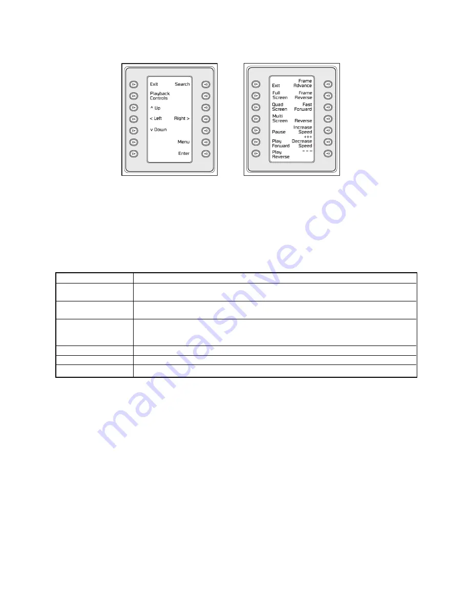
DVR1 Controls

DVR1 Playback Controls

Softkey

Functions 

Exit

*

•  Presents the previous keyboard menu (

RECORDER CONTROLS

).

•  Output signal of the Multiplexer is switched to MON A.

Playback Controls

•  Presents the DVR1 

PLAYBACK CONTROLS

menu (see 

Section 2.4.2

).

•  The Multiplexer is forced into 

Playback

mode to decode playback video from the DVR1.

Search

•  Presents the DVR1’s 

Search

screen. 

•  Video selected directly from this menu is not decoded unless the Multiplexer is in 

Play

mode.

Press 

PLAYBACK CONTROLS

on the DVR1 to properly view decoded video.

Up, Down, Left, Right

Navigate the DVR1’s menu screens

Enter

Equivalent to the DVR1’s 

Enter

command. 

Menu

Equivalent to the DVR1’s 

Menu

button. 

*

To stop playback and resume recording, 

EXIT

the 

DVR1 CONTROLS

and 

RECORDER CONTROLS

menus, 

then press 

PLAY

on the Multiplexer’s Main menu.

Summary of Contents for DVR1EP08

Page 1: ...DVR1 Series Single Channel Color Digital Video Recorder Applicable Models DVR1EP08 DVR1EP16 DVR1EP32 and DVR1EP32A Philips Communication Security Imaging Installation Instructions Eng ...

Page 2: ... touch dangerous voltage points or short out parts that could result in a fire or electric shock Never spill liquid of any kind on the unit 16 Servicing Do not attempt to service this unit yourself as opening or removing covers may expose you to dangerous voltage or other hazards Refer all servicing to qualified service personnel 17 Damage Requiring Service Unplug the unit from the outlet and refe...

Page 3: ...é conformément à la réglementation du Code Electrique National ou à la réglementation locale Disjonction de l alimentation Les appareils avec ou sans commutateurs ON OFF sont alimentés à chaque fois que le cordon d alimentation est branché à la source d alimentation toutefois les appareils disposant de commutateurs ON OFF ne fonctionnnent que lorsque le commutateur ON OFF est sur la position ON Le...

Page 4: ...sonas El símbolo de exclamación dentro de un triángulo equilátero se muestra con el objetivo de alertar al ususario de que instrucciones de operación y mantenimiento importantes acompañan al equipo Atención La instalación de este equipo debe ser realizada por personal capacitado solo en acuerdo y en cumplimiento de normas del National Electric Code Código Eléctrico Nacional ó las normas del Gobier...

Page 5: ...ET GEVAAR VAN BRAND OF ELEKTRISCHE SCHOKKEN TE VOORKOMEN DIENT U APPARATEN DIE NIET SPECIFIEK ONTWIKKELD ZIJN VOOR BUITENGEBRUIK NIET BLOOT TE STELLEN AAN REGEN OF VOCHT SICUREZZA Il simbolo triangolare di un fulmine con la punta a freccia intende mettere in allerta l utente riguardo alla presenza di tensioni pericolose non isolate all interno del guscio dell unità che potrebbero essere di intensi...

Page 6: ...ICOS NÃO EXPONHA À CHUVA OU HUMIDADE UNIDADES NÃO ESPECIFICAMENTE CRIADAS PARA UTILIZAÇÃO NO EXTERIOR ZASADY BEZPIECZEŃSTWA Błyskawica ze strzałką wewnątrz trójkąta równobocznego ma za zadanie zwrócić uwagę użytkownika na obecność nieizolowanego niebezpiecznego napięcia wewnątrz obudowy urządzenia o wielkości stwarzającej niebezpieczeństwo porażenia prądem Wykrzyknik wewnątrz trójkąta równoboczneg...

Page 7: ...eters 16 4 6 Configuring On screen Display Options 17 4 7 Managing Archive Storage 17 4 8 Accessing the Advanced Menu 19 4 9 About DSR 19 SECTION 5 DVR1 ADVANCED MENU PROGRAMMING 20 5 1 Overview of the DVR1 Advanced Menu 20 5 2 DVR1 Passwords 20 5 3 Overwriting the Hard Disk 21 5 4 Erasing Deleting and Recovering Hard Disk Data 21 5 5 Invoking Audio Recording 21 5 6 Using the Auto Delete Feature 2...

Page 8: ... C REO QUICK INSTALL GUIDE 33 1 1 Introduction 33 1 2 Required Software Version 33 1 3 Installation 33 1 3 1 Connection of Audio Video Cable A V cable 33 1 3 2 Connection of Alarm Contact 33 1 4 Programming the REO System Monitor 34 1 5 Programming the DVR1 34 1 6 Remote Viewing Considerations 34 APPENDIX D INSTALLATION GUIDE FOR THE COMBINED PHILIPS MULTIPLEXER INTUIKEY KEYBOARD DVR1 SERIES SYSTE...

Page 9: ...ific Region 65 350 1859 NOTE The shipping carton and all packing materials should be retained in case transporting the unit is necessary This will ensure safe transport of all components 1 3 Understanding the DVR1 Series The DVR1 Series of Digital Video Recorders provide a digital alternative to traditional time lapse VCRs Digital video recording allows continuous recording on a hard disk eliminat...

Page 10: ...ly UPS 3 Accessory I O Port Used to connect peripheral devices such as alarm devices alarm relays or theVEXT Video External Pulse connection see additional pertinent information including pinout details in this section 4 SCSI Port For connecting a SCSI compatible archive device 5 RS 232 Serial Port Serial port for Flash Upgrading of software Also used for external control of unit NOTE The RS 232 p...

Page 11: ...urchase a female DB 9 connector and perform wiring and connections as detailed in the following pin out Pin 1 Alarm In Pin 6 Error Out Pin 2 Alarm Out Pin 7 Ground Pin 3 Record Start In Pin 8 Videoloss Out Pin 4 Alarm Record Reset Pin 9 Disk End Out future feature Pin 5 VEXT Pulse Out Pin 10 Ground NOTE Refer to the multiplexer and other peripheral device manuals for pertinent connection and synch...

Page 12: ... Normal and Alarm NOTE Use of the VEXT connection is highly recommended when connecting the unit to a multiplexer Error Out The Error Out signal is activated when the unit experiences any operational or internal error Videoloss Out The Videoloss Out signal is activated when the unit experiences loss of video on the selected video input Composite or S video In the event of loss of video VIDEOLOSS w...

Page 13: ...e certain commands 13 Rewind Button Press REWIND to perform high speed reverse playback NOTE Rewind is also used to navigate the menus and may be referred to in this manual as the left arrow button 14 Single Frame Advance Button Press this button to perform a single frame advance while in Pause mode NOTE Single Frame Advance is also used to navigate the menus and may be referred to in this manual ...

Page 14: ...e the Left Right Arrows to move between fields in the menu Press ENTER to select any item Use the Up Down Arrows to scroll through the values of that particular parameter To save changes and exit the pop up menu select OK and or press ENTER To exit the menu without making changes press MENU or select CANCEL and press ENTER Programming Notations in this Manual Throughout the programming sections in...

Page 15: ... DVR1 will activate an alarm condition when the unit detects a signal on the Alarm In connection of the Accessories PCB Parameter HARDWIRE ALARM ENABLE DISABLE Whether the DVR1 will activate an alarm condition corresponding to the teletext alarm signal of a multiplexer or other device Parameter TELETEXT ALARM ENABLE DISABLE Whether the DVR1 will sound its internal buzzer during an alarm condition ...

Page 16: ...Delete all recording schedule parameters are deleted NOTE The fields in the Timer Settings menu can be edited easily using the Left Right Arrows to move between fields and Up Down Arrows to scroll through the various options at each parameter When you finish setting the parameters press ENTER Use the Left Right Arrows to navigate then highlight OK and press ENTER 4 5 Configuring the Recording Para...

Page 17: ...ving On or Off Set Archive Overwrite mode Erase Disk Array Main Menu Archive Setup Selective Archive The Selective Archive feature allows archiving of recorded data from the hard disk of the DVR1 to an archive device If the archive device is a CD writer you must play back the archived video from a PC s CD ROM drive using the Remote Viewer software included with the DVR1 package The Archive Search ...

Page 18: ... Filters menu as described previously When the search completes a Restore Search Results menu appears Main Menu Archive Setup Background Archive This archive feature enables automatic and continuous archiving in the background while other system operations continue i e all information going to the DVR1 hard drive is continuously sent to the DVAA Series Disk Array If this mode is enabled the archiv...

Page 19: ...ound Archive must be set to OFF To erase the archived data press ENTER The Erasing Media progress bar appears Press ENTER to cancel When the unit is finished erasing the pointers to the data the message box at right appears Press ENTER to acknowledge the message 4 8 Accessing the Advanced Menu For information on accessing the Advanced Programming menu please refer to Section 5 in this manual Note ...

Page 20: ...the DVR1 to its original factory default settings This password cannot be altered and is set permanently at 0000 Accessing the Advanced Menu Using the Password 1 Select ADVANCED MENU from the Main Menu then press ENTER The Password Box appears 2 Enter the Advanced Menu password Use the Up Down Arrows to select a character then press ENTER to move to the next character 3 Pressing ENTER on the last ...

Page 21: ...n this mode the unit never stops recording note that the LCD display does not count down the remaining time till the hard disk is full 5 4 Erasing Deleting and Recovering Hard Disk Data Advanced Menu Disk Maintenance Three options are provided for disk maintenance Delete Video Once video has been deleted it may be restored with the Undelete option if the video has not been overwritten Undelete Vid...

Page 22: ...proper playback NOTE If a single camera input is connected to the unit select NONE NOTE The list of compatible multiplexers continues to expand Please see the Bosch Web site at www philipscsi com for the most current listing 5 9 Adjusting Picture Qualities Advanced Menu Adjust Picture Use this menu to specify the Brightness Contrast and Saturation of the video input Adjustments made to the video i...

Page 23: ... access to the menu Use the Up Down Arrows to select a character then press ENTER and move to the next character Pressing ENTER on the last character opens the Confirmation Box Reenter the New password Pressing ENTER on the last character completes the password selection If the password in the Confirmation Box matches the password from the Password Box the message at right will appear Press ENTER ...

Page 24: ...peed is indicated on the LCD and can be altered using Up Down Record Speed or in the menu system For information about altering the normal record speed from the menu system see Section 4 5 The normal record speed can be altered while the unit is recording The unit continues recording while the menu system is active Alarm Recording When an alarm condition is detected the unit automatically switches...

Page 25: ...nly one recording session on the hard disk the unit will indicate START OF DATA on the primary monitor Playback Speed The unit plays back the data at the rate at which it was recorded The user can alter the playback speed using Up Down Record Speed Altering the playback speed overrides the speed of any incoming alarms To clear the override press STOP then PLAY to resume playback at the speed that ...

Page 26: ...idered to be a separate recording session To enter the Search Filters menu press SEARCH The Search Filters menu is displayed on the primary monitor Use this screen to specify the following Start and stop date of the search Start and stop time of the search Which cameras to search exclusively Which recorded alarms are to be searched Use the Left Right Arrows to navigate between the various fields i...

Page 27: ...e remote viewer software can be utilized PC Software No cost for archive Device Use the remote viewer software to retrieve video from the DVR s hard drive to a PC s hard drive No Disk Analysis feature is available Typical Usage After an incident is identified the video segment is isolated and then stored on a PC The file can then be stored on a network or some other storage medium 7 2 Using CD Wri...

Page 28: ...place tighter restrictions on it until the search results return a file size that can be archived When multiple small files are selected for archive the total available space on the CD must be less than 550MB CD archiving supports multiple sequential recording sessions This allows the recording of a video clip ejecting the CD inserting the same CD at a later time for the recording of sequential vi...

Page 29: ...ontact the local Bosch Representative for Services Service Centers U S A Phone 800 366 2283 or 408 956 3895 fax 800 366 1329 or 408 956 3896 e mail NationalServiceCenter ca slr com Canada 514 738 2434 Europe Middle East Asia Pacific Region 32 1 440 0711 For additional information see www philipscsi com All of our products now come with a 3 year warranty recorder heads monitor tubes and TC model pa...

Page 30: ...us Overwrite Archive Overwrite Mode Continuous Overwrite Auto Delete Mode 30 Days Background Archive Mode Off Input Composite Front Panel Locked Off Brightness 50 Contrast 50 Saturation 50 Display Current Time and Date Off Display Record Capacity Off Display Archive Status Off Display Last Alarm Off Record Playback Speed Off Display Playback Time and Date Off Baud Rate 9600 Hardwire Alarm Enabled ...

Page 31: ...DB 9 Connector SCSI 2 Port 50 pin male high density SCSI 2 connector RS 232 Serial Port DB 9 Connector S Video In 4 pin mini DIN connector see caution below S Video Out 4 pin mini DIN connector Composite Video In BNC connector see caution below Composite Video Out BNC connector CAUTION Do not connect both video inputs at the same time AUDIO VIDEO Video Signal Input 0 7 to 1 4 Volts peak to peak wi...

Page 32: ...120500 For DVAA Disk Arrays All Models TOP 250SSA 4010 0019 Accessories PCB 0900 0127a Rack Mount Kit 0110 R301 Fits 1U 19 inch rack unit Installation Instructions this manual 3935 890 3681 where is incremented with each revision cycle Wave Reader Manual 3935 890 4451 where is incremented with each revision cycle Wave Watch Manual 3935 890 4471 where is incremented with each revision cycle Wave Re...

Page 33: ... DVR1 also has audio recording capabilities connect the RCA connectors to AUDIO IN and AUDIO OUT of the DVR1 ATTENTION AUDIO IN of the A V cable must be connected to AUDIO OUT of the DVR1 AUDIO OUT of the A V cable must be connected to AUDIO IN of the DVR1 1 3 2 Connection of Alarm Contact In case of an alarm the output relay contact of the REO System Monitor can change the recording speed from No...

Page 34: ...ng pertains to the Remote Viewer Software included with the DVR1 allows Remote Viewing of video via a PC with this software loaded The Ethernet port connection depends on the network configuration For a DVR1 connected directly to a Hub use a Straight Through cable For a DVR1 connected directly to a PC use a Crossover cable For a DVR1 connected via standard phone line POTS using LAN modems refer to...

Page 35: ...ideo synchronization between the Multiplexer and DVR1 as follows Vext Pulse Out DVR1 Pin 5 to Multiplexer Pin 21 Ground DVR1 Pin 7 to Multiplexer Pin 25 4 Multiplexer Setup refer to the Multiplexer s Instruction Manual for further details Connect the Monitor to MON A output of the Multiplexer Execute the following Multiplexer Advanced Menu commands ADVANCED SETUP VCR SETUP RECORD SETUP VCR OUT VEX...

Page 36: ...N A display becomes locked in this mode To force the Multiplexer out of DVR1 CONTROLS mode execute the following command via the Multiplexer front panel ALT 1 VCR SEQ 4 If the Multiplexer was placed in Menu mode via front panel buttons and the IntuiKey keyboard goes into DVR1 CONTROLS the Multiplexer remains in Multiplexer Menu mode However the DVR1 CONTROLS keys on the IntuiKey keyboard will stil...

Page 37: ...s they perform Softkey Functions Exit Presents the previous keyboard menu DVR1 CONTROLS Output signal of the DVR1 is switched to MON A Full Quad Multi Presents the various viewing options of the multiplexer Pause Play Forward Play Reverse Equivalent to the DVR1 s front panel buttons Frame Advance Frame Reverse Fast Reverse Fast Forward Increase Speed Decrease Speed ...

Page 38: ...tring Place the hexadecimal value of the desired ASCII character into the command string entering two digit values for Year Month Day Hour and Minute into the command string The year is a 2 digit number and the time is military time 24 hour clock See the example to follow START END COMMAND CHARACTERS 1 2 3 4 5 Play Forward FPL 02 46 50 4C 03 Record REC 02 52 45 43 03 Stop STO 02 53 54 4F 03 Pause ...

Page 39: ...n Used in ASCII Character of Hex Value Entered Value Column Desired Value into Command String Year Character 1 y1 0 30 Year Character 2 y2 0 30 Month Character 1 m1 1 31 Month Character 2 m2 2 32 Day Character 1 d1 2 32 Day Character 2 d2 5 35 Hour Character 1 h1 1 31 Hour Character 2 h2 4 34 Minute Character 1 f1 3 33 Minute Character 2 f2 9 39 COMMAND 1 2 3 4 5 6 7 8 9 10 11 12 13 14 15 16 17 18...

Page 40: ...are registered trademarks of Microsoft Corporation Pentium is a registered trademark of Intel Corporation 3935 890 36813 03 02 2003 Bosch Security Systems Inc Printed In U S A All Rights Reserved Philips is a registered trademark of Philips Electronics N V Updated January 06 2003 Data subject to change without notice Refer to www philipscsi com for latest information ...

Reviews: