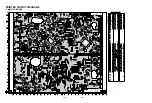


3-65
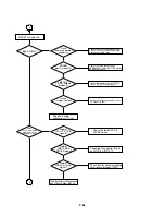
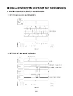
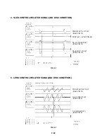
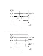
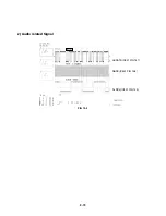
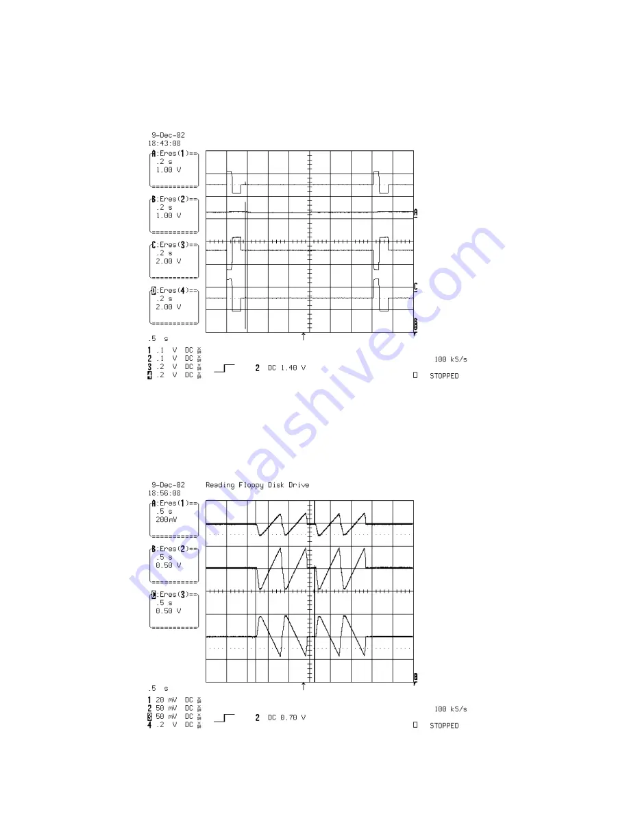
4. SLED CONTROL RELATED SIGNAL (NO DISC CONDITION)
FMSO(2.0V/1.4V/1.0V)
(IC501 PIN 19)
STBY(5V) – (IC201 PIN 50)
SL+(4.7V/3.6V/1.9V)
(IC202 PIN 12)
SL-(5.3V/3.7V/2.5V)
(IC202 PIN 13)
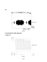
FIG 4-1
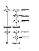
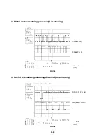
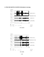
5. LENS CONTROL RELATED SIGNAL(NO DISC CONDITION)
FOSO(1.5V/1.4V/1.3V)
(IC501 PIN 12)
F+(4.0V/3.6V/3.2V)
(IC202 PIN 9)
F-(4.0V/3.6V/3.2V)
(IC202 PIN 8)
FIG 5-1
Summary of Contents for DVD755VR
Page 8: ...Directions for Use ...
Page 9: ......
Page 10: ......
Page 11: ......
Page 12: ......
Page 13: ......
Page 14: ......
Page 15: ......
Page 16: ......
Page 17: ......
Page 18: ......
Page 19: ......
Page 20: ......
Page 21: ......
Page 22: ......
Page 23: ......
Page 24: ......
Page 25: ......
Page 26: ...Personal Notes ...
Page 49: ......
Page 56: ...3 32 3 33 2 TU IF NICAM A2 CIRCUIT DIAGRAM EE MODE VIDEO TU MODE AUDIO COMBI SCART ...
Page 59: ...3 38 3 39 5 SCART JACK CIRCUIT DIAGRAM OPTIONAL PART COMBI SCART ...
Page 61: ...3 42 3 43 7 TIMER CIRCUIT DIAGRAM ...
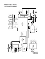
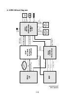
Page 65: ...3 50 3 51 PRINTED CIRCUIT DIAGRAMS 1 MAIN P C BOARD LOCATION GUIDE ...
Page 66: ...3 52 3 53 2 SMPS P C BOARD LOCATION GUIDE 3 TIMER P C BOARD LOCATION GUIDE 4 KEY P C BOARD ...
Page 67: ......
Page 93: ......
Page 96: ...3 83 3 84 3 AUDIO CIRCUIT DIAGRAM COMBI SCART MTK 03 3 25 SR17447A ...
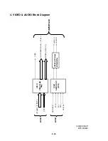
Page 97: ...3 85 3 86 4 AV JACK CIRCUIT DIAGRAM COMBI SCART MTK 03 3 25 SR17446A ...
Page 100: ...3 91 3 92 PRINTED CIRCUIT DIAGRAMS 1 MAIN P C BOARD LOCATION GUIDE ...
Page 101: ......
Page 133: ...MEMO ...
Page 134: ...EXPLODED VIEW 1 Deck Mechanism Exploded View 5 1 CONTENTS SECTION 5 MECHANISM OF DVD PART ...


