


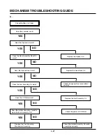


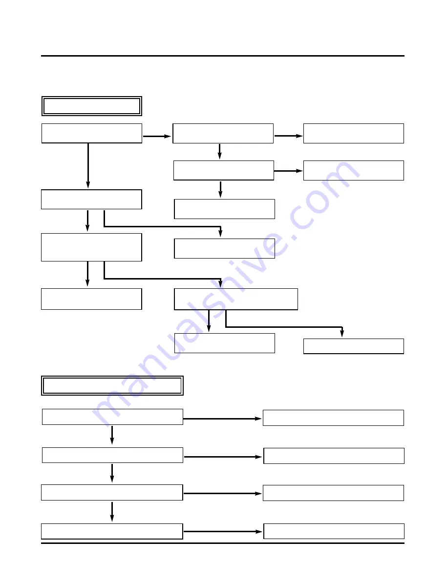
MECHANISM TROUBLESHOOTING GUIDE
4-26
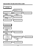
Cassette cannot be inserted.
Does the Lever Assembly
Switch work?
Is the Lever Assembly Switch
Spring damaged or omitted?
Does the CST IN Switch work
normally?
Replace or add the Lever
Assembly Switch Spring.
Is the Vcc of Main P.C.Board
5V?
YES
YES
Check the syscon circuit.
YES
Check the power circuit.
NO
Is the voltage between cassette
switch and GND on Main
P.C.Board 5V??
YES
Is there a short circuit between cassette
switch and GND on main P.C.Board?
Remove the short circuit part or
Replace the main P.C.Board.
NO
Check the Mode switch location
and syscon circuit.
Replace the CST IN Switch.
YES
NO
YES
NO
NO
Replace the CST IN Switch.
NO
NO
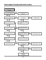
Cassette does not eject.
Does the L/D Motor rotate in reverse?
Check the L/D Motor or Drive IC.
Replace the Lever Assembly Switch.
Does the Lever Assembly Switch work?
YES
NO
NO
Does the Arm Assembly F/L work normally?
YES
NO
Does the Opener Door work?
YES
Replace the Arm Assembly F/L.
Replace the Opener Door.
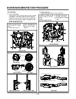
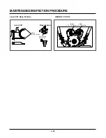
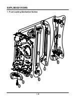
2. Front Loading Mechanism
A.
B.
Summary of Contents for DVD755VR
Page 8: ...Directions for Use ...
Page 9: ......
Page 10: ......
Page 11: ......
Page 12: ......
Page 13: ......
Page 14: ......
Page 15: ......
Page 16: ......
Page 17: ......
Page 18: ......
Page 19: ......
Page 20: ......
Page 21: ......
Page 22: ......
Page 23: ......
Page 24: ......
Page 25: ......
Page 26: ...Personal Notes ...
Page 49: ......
Page 56: ...3 32 3 33 2 TU IF NICAM A2 CIRCUIT DIAGRAM EE MODE VIDEO TU MODE AUDIO COMBI SCART ...
Page 59: ...3 38 3 39 5 SCART JACK CIRCUIT DIAGRAM OPTIONAL PART COMBI SCART ...
Page 61: ...3 42 3 43 7 TIMER CIRCUIT DIAGRAM ...
Page 65: ...3 50 3 51 PRINTED CIRCUIT DIAGRAMS 1 MAIN P C BOARD LOCATION GUIDE ...
Page 66: ...3 52 3 53 2 SMPS P C BOARD LOCATION GUIDE 3 TIMER P C BOARD LOCATION GUIDE 4 KEY P C BOARD ...
Page 67: ......
Page 93: ......
Page 96: ...3 83 3 84 3 AUDIO CIRCUIT DIAGRAM COMBI SCART MTK 03 3 25 SR17447A ...
Page 97: ...3 85 3 86 4 AV JACK CIRCUIT DIAGRAM COMBI SCART MTK 03 3 25 SR17446A ...
Page 100: ...3 91 3 92 PRINTED CIRCUIT DIAGRAMS 1 MAIN P C BOARD LOCATION GUIDE ...
Page 101: ......
Page 133: ...MEMO ...
Page 134: ...EXPLODED VIEW 1 Deck Mechanism Exploded View 5 1 CONTENTS SECTION 5 MECHANISM OF DVD PART ...


