


3-7
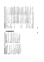
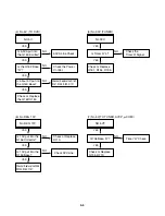
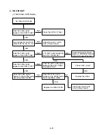
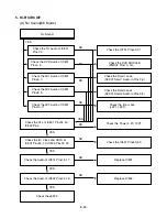
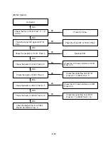
2. SYSTEM/KEY CIRCUIT
(1) AUTO STOP
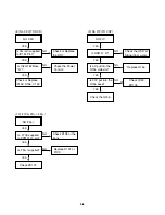
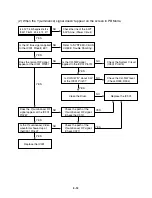
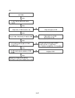
(2) The unstable loading of a Cassette tape
Auto Stop
Does the SW25 waveform
appear at the IC501
Pin105?
Do the T-UP Reel Pulses
appear at the IC501 Pin49?
Is 12V applied to the
PMC01 Pin8?
Check the Drum Motor
signal.
Does 5.2V appear at the
RS501?
Check the Power Circuit.
Check the Power.
Is 5.3V applied to the
R544 ?
Refer to SMPS 5.3VA
troubleshooting.
Check the IC501
Pins68, 69, 70, 71.
Do T/UP Reel Pulses
appear at the Q514
Base terminal ?
Replace the T/UP Reel
Sensor (RS501).
Check the CST SW and
the peripheral circuitry.
Replace the IC501.
The unstable loading of a
Cassette tape
Does the “H” signal appear
at the IC501 Pin30 during
inserting the CST ?
Does the “L” signal appear
at the IC501 Pin72 during
inserting the CST?
Check the Deck
Mechanism.
Caution :
Auto stop can occur because Grease or Oil is dried up
YES
YES
YES
NO
YES
YES
YES
YES
NO
NO
NO
NO
NO
NO
NO
YES
YES
YES
Summary of Contents for DVD755VR
Page 8: ...Directions for Use ...
Page 9: ......
Page 10: ......
Page 11: ......
Page 12: ......
Page 13: ......
Page 14: ......
Page 15: ......
Page 16: ......
Page 17: ......
Page 18: ......
Page 19: ......
Page 20: ......
Page 21: ......
Page 22: ......
Page 23: ......
Page 24: ......
Page 25: ......
Page 26: ...Personal Notes ...
Page 49: ......
Page 56: ...3 32 3 33 2 TU IF NICAM A2 CIRCUIT DIAGRAM EE MODE VIDEO TU MODE AUDIO COMBI SCART ...
Page 59: ...3 38 3 39 5 SCART JACK CIRCUIT DIAGRAM OPTIONAL PART COMBI SCART ...
Page 61: ...3 42 3 43 7 TIMER CIRCUIT DIAGRAM ...
Page 65: ...3 50 3 51 PRINTED CIRCUIT DIAGRAMS 1 MAIN P C BOARD LOCATION GUIDE ...
Page 66: ...3 52 3 53 2 SMPS P C BOARD LOCATION GUIDE 3 TIMER P C BOARD LOCATION GUIDE 4 KEY P C BOARD ...
Page 67: ......
Page 93: ......
Page 96: ...3 83 3 84 3 AUDIO CIRCUIT DIAGRAM COMBI SCART MTK 03 3 25 SR17447A ...
Page 97: ...3 85 3 86 4 AV JACK CIRCUIT DIAGRAM COMBI SCART MTK 03 3 25 SR17446A ...
Page 100: ...3 91 3 92 PRINTED CIRCUIT DIAGRAMS 1 MAIN P C BOARD LOCATION GUIDE ...
Page 101: ......
Page 133: ...MEMO ...
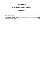
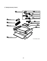
Page 134: ...EXPLODED VIEW 1 Deck Mechanism Exploded View 5 1 CONTENTS SECTION 5 MECHANISM OF DVD PART ...


