


3-19
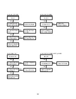
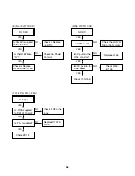
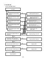
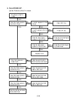
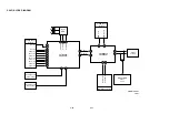
(B) No Sound
No Sound.
Check the Vcc of IC751 Pins1, 11, 19,
22, 33.
YES
Check 5.2V Line.
NO
Check the Tuner SiF signal at IC751
Pin2.
YES
Check the oscillator of IC751 Pins5, 6.
YES
Check the Audio of IC751 Pins30, 31.
YES
Check the Audio of IC801 Pins2, 3.
YES
Check the Audio of IC801 Pins16, 17.
YES
Check the Audio of IC802 Pins22, 26.
YES
Check the Signal flow from IC802
Pins22, 26, SC901 Pins1, 3.
YES
Check the Tuner SIF of TU701 Pin22.
NO
Replace X751
NO
Check the IIC Clock and Data at IC751
Pins12, 13.
NO
Check the signal flow from IC751
Pins30, 31 to IC801 Pins2, 3.
NO
Check the IIC Clock and Data at IC801
Pins42, 43.
NO
Check the signal flow from IC801
Pins16, 17 to IC802 Pins10, 16.
NO
Summary of Contents for DVD755VR
Page 8: ...Directions for Use ...
Page 9: ......
Page 10: ......
Page 11: ......
Page 12: ......
Page 13: ......
Page 14: ......
Page 15: ......
Page 16: ......
Page 17: ......
Page 18: ......
Page 19: ......
Page 20: ......
Page 21: ......
Page 22: ......
Page 23: ......
Page 24: ......
Page 25: ......
Page 26: ...Personal Notes ...
Page 49: ......
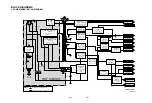
Page 56: ...3 32 3 33 2 TU IF NICAM A2 CIRCUIT DIAGRAM EE MODE VIDEO TU MODE AUDIO COMBI SCART ...
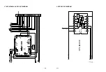
Page 59: ...3 38 3 39 5 SCART JACK CIRCUIT DIAGRAM OPTIONAL PART COMBI SCART ...
Page 61: ...3 42 3 43 7 TIMER CIRCUIT DIAGRAM ...
Page 65: ...3 50 3 51 PRINTED CIRCUIT DIAGRAMS 1 MAIN P C BOARD LOCATION GUIDE ...
Page 66: ...3 52 3 53 2 SMPS P C BOARD LOCATION GUIDE 3 TIMER P C BOARD LOCATION GUIDE 4 KEY P C BOARD ...
Page 67: ......
Page 93: ......
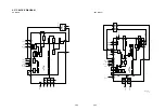
Page 96: ...3 83 3 84 3 AUDIO CIRCUIT DIAGRAM COMBI SCART MTK 03 3 25 SR17447A ...
Page 97: ...3 85 3 86 4 AV JACK CIRCUIT DIAGRAM COMBI SCART MTK 03 3 25 SR17446A ...
Page 100: ...3 91 3 92 PRINTED CIRCUIT DIAGRAMS 1 MAIN P C BOARD LOCATION GUIDE ...
Page 101: ......
Page 133: ...MEMO ...
Page 134: ...EXPLODED VIEW 1 Deck Mechanism Exploded View 5 1 CONTENTS SECTION 5 MECHANISM OF DVD PART ...