Toshiba VTV1402B, Service Manual
The Toshiba VTV1402B Service Manual is a comprehensive user guide available for free download on manualshive.com. This essential manual provides step-by-step instructions and troubleshooting tips to ensure optimum performance and longevity of your Toshiba VTV1402B television. Access your copy today and unlock the full potential of your device.
Share
Download


Reviews:
No comments
Related manuals for VTV1402B

37MD350B -
Brand: Magnavox Pages: 57

6620LDG
Brand: Sylvania Pages: 74

TLS-924
Brand: Sanyo Pages: 2

VHR-220 series
Brand: Sanyo Pages: 10

VHR-120 Series
Brand: Sanyo Pages: 11

VHR-150
Brand: Sanyo Pages: 19

VHR-150
Brand: Sanyo Pages: 28

VHR 390SP
Brand: Sanyo Pages: 32

VHP-VX50
Brand: Sanyo Pages: 35

TLS-S7000P
Brand: Sanyo Pages: 38

TLS-9024P
Brand: Sanyo Pages: 39

TLS-9072
Brand: Sanyo Pages: 41

TLS-1500P
Brand: Sanyo Pages: 38

TLS-4024P
Brand: Sanyo Pages: 46
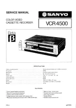
VCR 4500
Brand: Sanyo Pages: 56

TLS-4072
Brand: Sanyo Pages: 54

TLS-224P
Brand: Sanyo Pages: 181

TVD-2148
Brand: Denver Pages: 21


