Toshiba VTV2056, Service Manual
The Toshiba VTV2056 Service Manual is a comprehensive and essential resource for users of this high-performance television. It can be freely downloaded from manualshive.com, enabling users to access detailed instructions, troubleshooting tips, and maintenance guidelines to enhance their viewing experience and maximize the product's lifespan.
Share
Download


Reviews:
No comments
Related manuals for VTV2056

EWV401M
Brand: Emerson Pages: 16
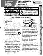
EWV401A
Brand: Emerson Pages: 8

EWV401B
Brand: Emerson Pages: 8

EWV401
Brand: Emerson Pages: 16

EV261
Brand: Emerson Pages: 28

EV477
Brand: Emerson Pages: 47

EWV401B
Brand: Emerson Pages: 83

EWV402M
Brand: Emerson Pages: 8

SR-MV40US2
Brand: JVC Pages: 10

SR-W5U - W-vhs Recorder/player
Brand: JVC Pages: 36

TIMELAPSE SR-S990E
Brand: JVC Pages: 34

SR-V101US - S-vhs Videocassette Recorder
Brand: JVC Pages: 28

SR-V101US - S-vhs Videocassette Recorder
Brand: JVC Pages: 52

SR-L911US
Brand: JVC Pages: 56

SR-L911UB
Brand: JVC Pages: 54

SR-VD400E
Brand: JVC Pages: 60

SR-V10E
Brand: JVC Pages: 68

SR-TS1U - Super Vhs Et Player Recorder
Brand: JVC Pages: 72


