


Below are a few more comments.
Motor:
The distance between rotor and stator is approx.
0.2 mm
, so that the rotor can be centered with small
shims of that size.
Pick-up arm:
The pick-up arm is clamped to the hollow shaft of the caliper spring/steering hook with the clamping
bracket
(93) FIG 8
.
Pick-up bearing:
By removing the adjusting ring (
90) FIG 8
., the entire steering hook can be removed.
Watch out
for the
bearing balls
and also the spacer falls out
70 FIG 8
Platen-printer:
By loosening the fastening screws at the foot of the disc-press/plate presser, it can be removed. After
removal of the clamping ring (
103) FIG 8
, the guide rod can be pushed out of the ball bush.
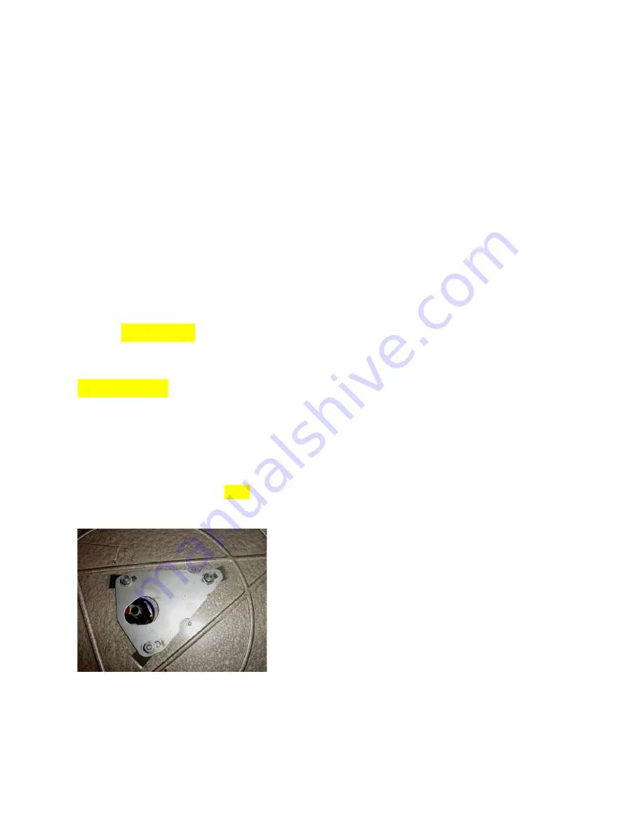
Mechanism:
After removal of the turntable (
C clip
/clamping
ring 64
)
FIG 8,
the entire mechanism can be removed by
removing the 3 nuts.
In advance, the various connections must first be disconnected. The top plate (
N fig. 8
) can be moved in
the direction of the main axis/ shaft thanks to the oblong/slotted holes. In order to prevent deformation
of the main axis, when the platform is pressed, the distance between main axis and plate must be as
small as possible.
25
Summary of Contents for AG1000
Page 29: ...See also DSC00130 jg and stitched 00125 00128 and zippy1 fig 6 jpg 29 ...
Page 56: ...56 ...
Page 61: ...Runnells IA usa c60h hotmail com 61 ...
Page 62: ...62 ...
Page 63: ...63 ...
Page 64: ...64 ...
Page 65: ...FIG 8 65 ...
Page 66: ...FIG 8 FIG 9 66 ...
Page 67: ...FIG 9 67 ...
Page 68: ...68 ...
Page 69: ...THERE IS NO 32 THRU 40 WAS NONE 69 ...
Page 70: ...70 ...
Page 71: ...71 ...


