background image


PAN03 already installed in a wall box. To solve this issue, PAN03 support a special 

featur

e that can use S1 or S2 to execute “exclusion, inclusion, Reset or Association” 

at the first 3 minutes when first time connect to main power. PAN10 does not support 

S1/S2 function.


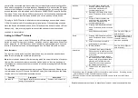
LED Indication


To distinguish what mode the switch is in, view from the LED for identification. 
 

State Type


LED Indication


Normal


Whenever we switch On and off of the PAN03/PAN10 by S1 S2 or 
On/Off button or RF command, the LED will lights up 1 second and 
then off.


No node ID


Under normal operation, when the Switch has not been allocated a 
node ID, the LED flashes on and off alternately at 2-second 
intervals. By pressing S1 S2 or On/Off button, it will stop flashing 
temporarily. 


Learning


When PAN03/PAN10 is in learning mode, LED flashes on and off 
alternately and repeatedly at 0.5 second intervals.


Overload


When overload state occurs, the Switch is disabled of which LED 
flashes on and off alternately at 0.2 second intervals. Overload 
state can be cleared by unplugging and reconnecting the Switch to 
the wall outlet.


Choosing a Suitable Location 
 

1. 

Do not locate the Switch facing direct sunlight, humid or dusty place. 

2. 

The suitable ambient temperature for the Switch is 0°C~40°C. 

3. 

Do not locate the Switch where exists combustible substances or any source of 
heat, e.g. fires, radiators, boiler etc. 

4. 

After putting it into use, the body of Switch will become a little bit hot of which 
phenomenon is normal.


Installation 
 

1.  Put the in wall switch into a wall box and connect the AC power wire L,N to 

PAN03/PAN10 connector L, N. 

 
2.  Connect the wall switch to the PAN03/PAN10 as Fig1. 
 

3.  There are 3 mode PAN03/PAN10 can be configured to match different kind of wall 

switch, 

please refer to 

3-10 Edge / Pulse / Edge-Toggle mode 

which described in next 

section of this user manual. 


Programming


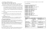
1.    Basic Command Class / Binary Switch Command Class


The  Switch  will  respond  to  BASIC  and  BINARY  commands  that  are  part  of  the 
Z-Wave system. 


1-1 BASIC_GET / BINARY_SWITCH_GET 

        Upon receipt of the following commands from a Z-Wave Controller, the Switch will 

report its On/Off state to the node asked. 


Basic Get Command: 

[Command Class Basic, Basic Get]


Basic Report Command: 
Report OFF: 

[Command Class Basic, Basic Report, Value = 0(0x00)]


Report ON:

[Command Class Basic, Basic Report, Value = 255(0xFF)]


Binary  Switch  Get  Command:

[Command  Class  Switch  Binary,  Switch 

Binary Get]


Binary Switch Report Command: 
Report OFF:

[Command Class Switch Binary, Switch Binary Report, Value 

=0(0x00)]


Report ON:

[Command Class Switch Binary, Switch Binary Report, Value = 

255(0xFF)]


1-2 BASIC_SET / SWITCH_BINARY_SET 

        Upon  receipt  of  the  following  commands  from  a  Z-Wave  Controller,  the  load 

attached to the Switch will turn on or off. 


[Command  Class  Basic,  Basic  Set,  Value  =  1~99,255(0xFF)]

:  the  load 

attached to the Switch turns on.


[Command  Class  Basic,  Basic  Set,  Value  =  0(0x00)]

:  the  load  attached  to 

the Switch turns off.


Summary of Contents for Z-Wave Plus PAN03

Page 1: ... OFF switch PAN03 PAN10 is a security enabled wireless switch based on Z Wave Plus technology Z Wave Plus TM enabled devices displaying the Z Wave Plus TM logo can also be used with it regardless of the manufacturer and can also be used in other manufacturer s Z Wave TM enabled networks Remote On Off ...

Page 2: ...tton on the Switch The table below lists an operation summary of basic Z Wave functions Please refer to the instructions for your Z Wave TM Certificated Primary Controller to access the Setup function and to include exclude associate devices Function Description Annotation No node ID The Z Wave Controller does not allocate a node ID to the Switch 2 second on 2 second off Inclusion 1 Put your Z Wav...

Page 3: ...tors boiler etc 4 After putting it into use the body of Switch will become a little bit hot of which phenomenon is normal Installation 1 Put the in wall switch into a wall box and connect the AC power wire L N to PAN03 PAN10 connector L N 2 Connect the wall switch to the PAN03 PAN10 as Fig1 3 There are 3 mode PAN03 PAN10 can be configured to match different kind of wall switch please refer to 3 10...

Page 4: ... 0x02 Size 4 Meter Value W 2 1 3 Overload alarm report When PAN03 PAN10 detects the current is more than 12A it will send Alarm Report to Group 1 node The content of Alarm Report Alarm report command Command_Class_Alarm Alarm_Report Alarm Type 0x08 Alarm Level 0xFF 2 2 Response to Meter Get Command The Switch will report its 1 instant Power Consumption Watt or 2 accumulated power consumption KWH o...

Page 5: ...alue 2 230 5 V 2 2 5 AC load current I When receiving Meter Get Command it will report Meter Report Command to the node Meter Get Command Command Class Meter Meter Get Scale 0x05 I Meter Report Command Command Class Meter Meter Report Rate Type 0x01 Meter Type 0x01 Precision 2 Scale 0x05 Size 2 Meter Value I Example Scale 0x05 I Precision 2 Size 2 2 Bytes of I Meter Value 1 0x01 I Meter Value 2 0x...

Page 6: ...Threshold of KWh for Load Caution This is a warning when the KWh of load over the preset threshold value if the setting value is 10000 when the Accumulated Power Consumption of Relay1 over this value PAN03 PAN10 will send KWH meter report to warn the Group1 node minimum value is 1KWh and default value is 10000 kWh 3 5 Restore switch state mode Whenever the AC power return from lost PAN03 PAN10 wil...

Page 7: ...earn function does not change because learning will not be protected 5 Firmware update over the air OTA PAN03 is based on 500 series SoC and supports Firmware Update Command Class it can receives the updated firmware image sent by controller via the Z wave RF media It is a helpful and convenient way to improve some function if needed 6 Command Classes The Switch supports Command Classes including ...

Page 8: ...g it into use the body of Module will become a little bit hot of which phenomenon is normal Warning 1 Plug out to disconnect from power supply Do not plug in line 2 Do not exceed the max rating Disposal This marking indicates that this product should not be disposed with other household wastes throughout the EU To prevent possible harm to the environment or human health from uncontrolled waste dis...

Page 9: ...on a circuit different from that to which the receiver is connected Consult the dealer or an experienced radio TV technician for help This device complies with Part 15 of the FCC Rules Operation is subject to the following two conditions 1 This device may not cause harmful interference and 2 This device must accept any interference received including interference that may cause undesired operation...

Reviews: