Phase 3 J-3 CUB 370 RTF Operating Instructions Manual Download Page 19

9

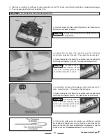
If you're flying the airplane and it seems to always want to turn right or left or pitch up or down, you can use the electronic trim tabs 
on the transmitter to correct these tendencies.  We suggest flying the airplane straight ahead and level, then letting go of the right-
hand control stick for a few seconds.  Watch what the airplane does.  It may pitch up or down, or it may turn right or left, or it may do 
a combination of these.  Do this several times to double-check your findings.  If the airplane does one of the following while in straight 
and level flight without your hand on the control stick, move the following electronic trim tab(s) to correct it:

  If the airplane pitches up:  Move the right-hand control stick vertical trim tab (elevator) forward a couple of clicks.

  If the airplane pitches down:  Move the right-hand control stick vertical trim tab (elevator) back a couple of clicks.

  If the airplane turns right:  Move the right-hand control stick horizontal trim tab (rudder) left a couple of clicks.

  If the airplane turns left:  Move the right-hand control stick horizontal trim tab (rudder) right a couple of clicks.

You can make these trim tab changes while you are flying, but we suggest having a friend move them for you so you don't 

lose sight of the airplane.  We also recommend moving the trim tabs only a couple of clicks at a time so you don't 
over-correct for the trim problem.

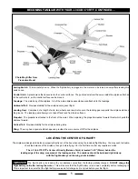
FLIGHT-TRIMMING THe J-3 CuB 370 RTF

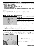
While you're flying your airplane, there comes a time when you might crash.  If the crash isn't too bad, most damage can be repaired 
quickly and easily.  If the damage is beyond repair, spare parts are available for purchase.  If a foam part is going to break during a 
crash it will usually break cleanly.  To repair a clean break, follow the procedures below:

  Glue the broken parts together, using a thin layer of 5 minute epoxy or white glue, following the directions on the glue bottle.  Hold 

the parts together and in alignment until the glue fully cures.

  Apply a strip of clear Scotch

®

 tape over the seams to strengthen the joint even more.


It is very important that you use no solvents or Cyanoacrylate (C/A) glue, which can damage foam.  If any of these 

chemicals comes in contact with the foam parts, the parts will be destroyed.  Use only epoxy or white glue to repair damaged 
foam parts.

FIXING MINOR CRASH DAMAGe

PRO TIP

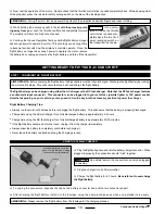
  Check before every flight to ensure that the batteries in the transmitter are working properly.  The needle in the voltage meter 

should be in the silver "safe" area.  Change the batteries when the needle falls into the red "unsafe" area.

  Before recharging the flight battery, let the motor run until the flight battery is discharged and the motor won't run any longer.  This 

will ensure you don't overcharge the flight battery.

  Do not recharge the flight battery if it is hot.  Wait for the flight battery to cool before recharging it.

  Never leave the flight battery plugged into the airplane unless you are flying or testing the controls.

  Before flying, always double-check that you've extended the transmitter antenna completely.

  Never cut or otherwise shorten the receiver antenna or you will lose control of the airplane in a very short distance.  Let the an-

tenna hang behind the back of the fuselage.

  Before each flight, do a quick motor test to make sure that the motor is producing full power.  If it isn't, you may need to charge the 

flight battery longer.  If using the AC wall charger, do not charge the flight battery longer than 3 hours.  If using the DC fast-charger, 
do not charge the flight battery more than one cycle (approximately 30 minutes).  Charging the flight battery longer than recommended 
can cause damage to the flight battery.  If the flight battery becomes hot to the touch, remove it from the charger immediately.

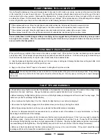
  Before each flight, double-check that the control surfaces are moving in the correct direction.  If they aren't, adjust the servo 

reversing switches on the transmitter as described on page # 3.

FLIGHT TIPS AND WARNINGS

Continued On Next Page


Summary of Contents for J-3 CUB 370 RTF

Page 1: ...gr Wing Loading 13 Ounces Per Square Foot 39 5gr dm2 Molded from Durable Plastic and Foam Preinstalled 4Ch FM 27MHz USA Radio Control System 35MHz EU Three Channel Control Elevator Rudder and Throttle...

Page 2: ...the flight battery may occur To prevent the flight battery from overheating during the charging process allow the flight battery to completely cool before recharging it Always completely discharge th...

Page 3: ...Assembly Fuselage Assembly Not Shown SmalL wood ScrewS 12 Landing Gear Wing Struts and Clips 4 Propeller and Spinner Phase 3 is proud to present the J 3 Cub This trainer aircraft is modeled after air...

Page 4: ...rsing Switches These switches allow you to electronically change the direction the servos move Throttle Control Stick This stick can move both right and left and up and down at the same time and is us...

Page 5: ...e airplane forward Vertical Tail Provides stability for the airplane during turns Wing The wing has a special airfoil shape and provides the main source of lift for the airplane The flight battery inc...

Page 6: ...CUB 370 RTF Step 1 Installing the Transmitter Batteries Continued On Next Page Step 2 Installing the horizontal tail Carefully slide the horizontal tail into the slot in the back of the fuselage When...

Page 7: ...nt portion of the vertical tail down into the mounting slot in the fuselage Push the vertical tail down in position When aligned properly the tab in the base of the vertical tail should fit into the n...

Page 8: ...the radio system later PRO TIP Carefully snap the plastic clevis on the pushrod wire into the outermost hole in the rudder control horn We suggest installing the clevis into the outermost hole in the...

Page 9: ...it firmly onto the front of the propeller The inside of the rubber safety spinner is molded to fit securely over the hex nut and threaded propeller shaft Step 7 Installing the wing Set the wing onto t...

Page 10: ...are four plastic wing struts included There are two longer ones for the front and two shorter ones for the rear When installing them in the next few procedures make sure to install the two front wing...

Page 11: ...ll need to make sure that the transmitter is turned on Turn on the transmitter The needle in the voltage meter should move into the silver safe area If it doesn t replace the batteries with a fresh se...

Page 12: ...he flight battery into the connector that is inside the fuselage When plugged in properly the connectors should click together IMPORTANT As a safety feature the connectors can only be plugged in one w...

Page 13: ...to the left The rudder should move left If the rudder does not move in the correct direction flip the CH 1 servo reversing switch on the front of the transmitter as shown PRO TIP Looking from the back...

Page 14: ...ips Always run the motor until it stops before recharging the flight battery This will ensure that the battery is properly discharged Charge time using the AC wall charger for a fully discharged batte...

Page 15: ...you become a proficient flyer you should always plan on flying your airplane when there s no wind We strongly sug gest waiting for a calm day If it s windy and you attempt to fly it will only make lea...

Page 16: ...will help ensure your success Some Things to Remember With the flight battery fully charged you can expect anywhere from 4 6 minutes of flight time so plan your landing accordingly Make sure that your...

Page 17: ...e ground making sure that the airplane is pointing directly into the wind Slowly push the throttle control stick forward until the motor is running at full power The airplane will quickly begin to acc...

Page 18: ...direction you want move the control stick gently in the opposite direction to level the wing then allow the control stick to return to center The longer you hold the control stick over the tighter th...

Page 19: ...ottle Hold the parts together and in alignment until the glue fully cures Apply a strip of clear Scotch tape over the seams to strengthen the joint even more It is very important that you use no solve...

Page 20: ...ally the transmitter charger and flight battery Do not allow any of the electrical components to get wet or damage may occur Periodically double check that the propeller nut is tight Check the propell...

Page 21: ...rystal Set Ch 3 PH109024 27MHz FM Crystal Set Ch 4 PH109025 27MHz FM Crystal Set Ch 5 PH109026 27MHz FM Crystal Set Ch 6 PH109028 Motor Controller Sorry No Photo Available PH109030 Receiver w o Crysta...

Page 22: ...ter trim tab as control input described on page 19 5 Airplane constantly climbs or A You are flying in too much wind A Fly when there is no wind descends without any B The airplane is out of trim adju...

Reviews: