DO2/Pin 9
Active high
yes
GND
no
6.2.3 RS-485
Connecting RS-485 via D-Sub
► Connect a Pfeiffer Vacuum control unit or an external PC via pin 13 and pin 14 at the D-Sub con-
nection of the electronic drive unit.
6.3 Connecting control unit
1
4
3
2
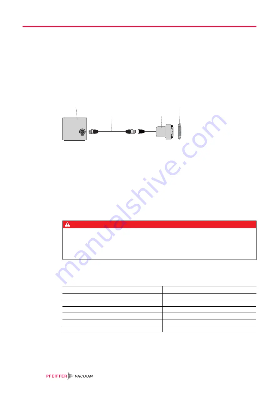
Fig. 12:
Connecting a control unit via the "remote" connection
1 Control unit
3
RS-485 to M12 adapter
2 M12 to M12 interface cable
4
"remote" connection
Procedure
► Use cables from the scope of delivery of the control unit, or from the accessories program.
► Install the interface cables between the “remote” connection and the “RS-485” connection of the
control unit.
– Tightening torque:
0.4 Nm
► Always connect the RS-485 interface to one external control unit only.
6.4 Using RS-485 interface
DANGER
Danger to life from electric shock
When establishing the voltages that exceed the specified safety extra-low voltage (according to IEC
60449 and VDE 0100), the insulating measures will be destroyed. There is a danger to life from elec-
tric shock at the communication interfaces.
► Connect only suitable devices to the bus system.
The interface designated “RS-485” is intended for connecting a Pfeiffer Vacuum control unit or a exter-
nal PC. The connections are galvanically safe and are isolated from the maximum supply voltage for the
electronic drive unit.
Designation
Value
Serial interface
RS-485
Baud rate
9600 Baud
Data word length
8 bit
Parity
none (no parity)
Start bits
1
Stop bits
1
Tbl. 8:
Features of the RS-485 interface
Interfaces
34/84
Summary of Contents for HISCROLL 12
Page 83: ...83 84...


