


Rev.: 2004-001-GB
10
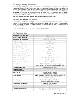
5.1 Generator suitability
The Electro Fusion Controllers of type
Monomatic
provide the following means to increase the generator
suitability:
•
Wide tolerance for input voltage and Input frequency.
•
Display of current input voltage and frequency.
•
Soft-Start for limitation of the generator load.
Despite this characteristics, the generators to be used have to fulfil the following requirements and
recommends, in order to avoid damaged of the control unit and to ensure that the internal monitoring
function of the control unit will not interrupt the welding process:
•
suitable to drive inductive loads and phase cut systems
•
no-load voltage adjustable to 240V – 260V at nominal 230V
(nominal 110V: 120V – 130V
(AC)).
•
output current of 18 Amps at one phase at nominal 230V (nominal 110V: 36Amps).
•
stable output voltage and engine speed, also at fast alternating loads
•
synchronous generators with mechanical speed control preferred
•
voltage peaks must no exceed 800V
Min. required generator output power 230V, 50Hz, 1-phase
Diameter
Output Power
20-75 mm
2kW
90-160 mm
3,2kW
180-710mm
4.5kW (mechanically controlled)
5kW (electronically controlled)
For generators with insufficient control performance or voltage control it has to be selected 3-3.5 times
higher output power than the stated ones to achieve an undisturbed operation. Electronically controlled
generators tent to oscillate with the control of the welding process, which can lead to high output voltage
peaks. Please, test suitability before using that kind of generators.
Manufactures like HONDA, EISEMANN, GEKO, FISCHER, PANDA and KIRSCH provide generators
performed especially for this kind of application.
Caution: 110V Control Units shall not be used at 230V power supply and vice versa.
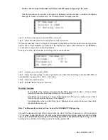
6 Starting a welding process
6.1 Preparation
Before starting you have to carry out the following steps in the given order:
1.
Check the device, cables and adapters visually. If necessary you have to replace them.
2.
Plug in Detachable welding cables.
3.
Unroll welding, power and extension cables completely.
4.
Switch of the Power Switch of the control unit.
5.
Start the generator before you plug in the control unit. Wait until the generator output
voltage has stabilized.
6.
Plug in the power cable of the control unit.
7.
Switch on the power switch.
Summary of Contents for monomatic
Page 2: ...Rev 2004 001 GB 2 Rev 2004 001 GB...
Page 6: ...Rev 2004 001 GB 6...
Page 19: ...Rev 2004 001 GB 19 9 Conformity Declaration...
Page 20: ...Rev 2004 001 GB 20...
Page 21: ...Rev 2004 001 GB 21...


