background image

Rev.: 2004-001-GB


5

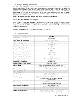
2.3  Range of fitting dimensions  

For which range of fitting dimensions a electro fusion control unit can be used depends essentially on the 
power consumption to the used fittings itself. Since the power consumption of the fittings are different for 
different  fitting  manufacturers,  a  general  statement  concerning  this  point  is  hardly  to  make.  In  case  of 
doubt,  each  single  case  has  to  be  checked  separately.  For  electro  fusion  control  units  of  the  type 

Monomatic

  the  following  general  statement  can  be  made,  with  the  assumption,  that  all  welding 

processes  were  made  one  after  the  other,  i.e.  that  the  control  unit  is  able  to  cool  down  during  the 
preparation time of the next fitting: 

Note: The Monomatic control unit can be used for FUSAMATIC fittings only. 

 
Use for dimension 

20-355mm

 without any limit. 

 
From  a  diameter  for 

400mm  and  higher

  there  must  be  provided  longer  off-times  to  ensure  a  cooling 

down  of  the  control  unit  (Error  message  “Device  too  hot”).  Before  processing  fittings  in  this  dimension 
range,  you  have  to  check  that  the  welding  current  of  the  fitting  does  not  exceed  the  maximum  output 
current of the control unit. 
 
All above made statements refer to an ambient temperature of 20°C. 


2.4  Technical data 

Technical Data – 

Technische Daten


Monomatic 

ISO 12176-2 Class 

- Klassifizierung


P

2

 3 U S

1

 F A M 

Input Voltage 

-


Eingangsspannung


230V ~/AC, (185V-300V) 

Input Current 

- Eingangsstrom 


16A 

Input Frequency

 - Eingangsfrequenz 


50Hz (40-70Hz) 

Output Voltage

 -


Ausgangsspannung


40V 

Output Current 

- Ausgangsstrom


60A (max.: 80A) 

 Power Consumption 

- Leistungsaufnahme


3200VA 

Temperature Range 

-


Arbeitstemperatur


-10°C - +50°C 

Protection Class


- Gerätesicherheit


IP54, Class 2 

Weight incl. Cables

 - Gewicht inkl. Kabel


18kg 

Main Supply Cable

 - Netzkabel


4,5 m (Euro-Plug – 

Euro-Stecker

Welding Cable

 - Schweißkabel 

5m (fixed – 

fest

Welding Terminals 

- Anschlußkontakt


4,7mm (opt. 4,0mm) 

Display 

- Display


4 x 20 Characters (alphanum.), background lighting


4 x 20 Zeichen (alphanumerisch), Hintergrundbeleuchtung


Dimension 

- Abmessungen


440mm x 380mm x 320mm 

Monitoring Functions - 

Überwachungsfunktionen


Input 

- Eingang


Voltage / Current / Frequency  

Spannung / Strom / Frequenz


Output 

- Ausgang


Voltage / Resistance / Contact / Short circuit / Current Monitoring 

Spannung / Widerstand / Kontakt / Kurzschluß / 

Stromüberwachung


Other - Sonstige


System / Working Temperature / Service  

System / Arbeitstemperatur / Wartung


Error Messages

 -


Fehlermeldung 

Plain Text / Acoustic Signal 

Klartext im Display / Dauerwarnton


Enclosed Parts 

- Lieferumfang


Control Box, Transport Box, Instructions Manual 

Gerät, Transportbox, Bedienungsanleitung


Summary of Contents for monomatic

Page 1: ...e G m b H Ka rl Br ge r St r 10 DE 36304 A lsfe ld T el 49 6631 9652 0 Fa x 49 6631 9652 52 System Welding Device PF monomatic PF Schwei technologie GmbH Karl Br ger Str 10 DE 36304 Alsfeld Tel 49 0 6...

Page 2: ...Rev 2004 001 GB 2 Rev 2004 001 GB...

Page 3: ...ontrols and Plugs 8 5 Power Connection 9 5 1 Generator suitability 10 6 Starting a welding process 10 6 1 Preparation 10 6 2 Welding with the FUSAMATIC Mode 12 7 Other Functions 14 7 1 Function menu 1...

Page 4: ...should be carried out more often During the maintenance the machine will be upgraded to the current technical state Additionally you get a 3 month function guarantee for the maintained device The main...

Page 5: ...er to an ambient temperature of 20 C 2 4 Technical data Technical Data Technische Daten Monomatic ISO 12176 2 Class Klassifizierung P2 3 U S1 F A M Input Voltage Eingangsspannung 230V AC 185V 300V Inp...

Page 6: ...Rev 2004 001 GB 6...

Page 7: ...ldren away Do not allow other people touch the device or cables keep them away from your working place 5 Store up your device safely Unused machines should be kept in a dry and locked room inaccessibl...

Page 8: ...Rev 2004 001 GB 8 4 Controls and Plugs 1 DISPLAY 2 START 3 STOP 7 6 5 4 4 Power Switch 5 Welding Cable 6 Cable Holder 7 Power Supply Cable...

Page 9: ...s shall not be used at 230V power supply and vice versa When operating on a electric distributor or the main power supply of nominal 230V a min 16 Amps slow fuse comprising a residual current operated...

Page 10: ...20 75 mm 2kW 90 160 mm 3 2kW 180 710mm 4 5kW mechanically controlled 5kW electronically controlled For generators with insufficient control performance or voltage control it has to be selected 3 3 5...

Page 11: ...input voltage In case of generator use check that the voltage is at about 240 260V at nominal 230V nominal 110V 120V 130V AC Line 3 shows the input frequency Line 4 indicates that no fitting in conne...

Page 12: ...elding time Line 3 shows the fitting type and welding voltage Line 4 shows error messages respectively You have to compare the shown parameters with the parameters stated on the fitting In the case th...

Page 13: ...r messages respectively The welding process will stop automatically when the actual time reaches the nominal time This will be indicated by two bleeps and the following message Act time 0200s Nom time...

Page 14: ...u item START short Moves the cursor upwards STOP short Moves the cursor downwards START 3 sec Selects the marked menu item STOP 3 sec Cancels the function menu 7 2 Adjusting the display contrast By se...

Page 15: ...the system configuration menu the display will show a list of language indicators GB SE ES The indicators stand for GB English SE Swedish ES Spanish IT Italian DK Danish PT Portuguese DE German FR Fr...

Page 16: ...Welding Terminal 4 7mm standard 1_0200_003 Welding Terminal 4 0mm standard 2_0200_003 Welding Terminal 4 7mm Fusamatic with detection tip 2_0200_004 Welding Terminal 4 0mm Fusamatic with detection ti...

Page 17: ...ature of transformer is too high Let the device cool down for about 45 min Emergency cut out Welding was interrupted by pressing the STOP key Welding is faulty Frequency error Input frequency out of w...

Page 18: ...tacts Use an other fitting Service The recommended service interval of 12 months or 200 working hours is exceeded The device has to be checked by an authorized service point The device is still usable...

Page 19: ...Rev 2004 001 GB 19 9 Conformity Declaration...

Page 20: ...Rev 2004 001 GB 20...

Page 21: ...Rev 2004 001 GB 21...

Reviews: