


Rev.: 2004-001-GB
16
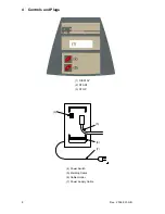
8 Trouble shooting
8.1 Replacing Welding Terminals
The welding plugs should be checked frequently. If necessary they can easily replace in no time.
1. Switch off the device and disconnect it from the mains supply or generator!
2. Slip off the PVC-cap over the welding terminal.
3. Hold the front part of the brass contact with a pipe wrench and screw the welding terminal with a 8mm-wrench
out of the brass contact.
4. The red welding cable has to be equipped by a welding terminal with detection tip! You have to use welding
terminals that are delivered by PF only!
5. Screw the new welding terminal tight into the brass contact and slip the PVC-cap over the welding terminal.
Pay attention, that the PVC-cap is slipped over so far, that the welding terminal is left blank for about 15mm.
1_0200_001
Welding Terminal 4.7mm, standard
1_0200_003
Welding Terminal 4.0mm, standard
2_0200_003
Welding Terminal 4.7mm, Fusamatic (with detection tip)
2_0200_004
Welding Terminal 4.0mm, Fusamatic (with detection tip)
1_0410_004
PVC-Cap, red
1_0410_003
PVC-Cap, black
8.2 Adapter
For different fitting types different adapters are needed. In the following table you will find a selection of
available adapters:
1_0200_005
FUSAMATIC-Adapter 4.7/4.7
1_0200_006
FUSAMATIC-Adapter 4.7/4.0
1_0200_007
FUSAMATIC-Adapter 4.0/4.7
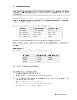
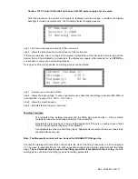
8.3 Start messages
After switching on the device the following message appears on the display:
PF-Monomatic
Version 2.04AH
25 Working hours
Row 1 and 2 show the
type
and
firmware revision
of the control box.
Row 3 counts the total
amount of working hours
(summed up fusion times).
After ten seconds the above shown display will disappear.
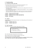
In the following there could be shown system messages like
error messages
of previous welding
cycles or
service notes
, which can be aborted by pressing the red STOP-key.
Summary of Contents for monomatic
Page 2: ...Rev 2004 001 GB 2 Rev 2004 001 GB...
Page 6: ...Rev 2004 001 GB 6...
Page 19: ...Rev 2004 001 GB 19 9 Conformity Declaration...
Page 20: ...Rev 2004 001 GB 20...
Page 21: ...Rev 2004 001 GB 21...


