background image

34 . TGA 8000 Installation and Hardware Guide 


6.


Click OK to accept the entries. 

7.


Click OK again to exit the Configuration dialog box or select Add Analyzer to add 

another analyzer to the configuration. Remember that the analyzer must be 

connected to the communications port and powered on, otherwise it will not be 

recognized by the Pyris software. 

Once Pyris Software has been configured for the TGA, the application can be started from 
Pyris Manager. 

Starting the Pyris Manager 

1.


Select Pyris Manager from the Pyris group under PerkinElmer Applications in 

All Programs on the Start menu. The Pyris Manager is displayed on the screen. 

2.


Select TGA 8000 from the Pyris Manager. The TGA application loads and the Control 

Panel is displayed. 

If you have an autosampler, you should now go to Autosampler Adjustment. 

Configure the iOS App for the TGA 8000 

This procedure will help guide you in configuring the TGA 8000 for use with an iPad/iPhone. 

The interface is designed so the Pyris Light app communicates with the TGA8000 via the PC 

which is connected to your company’s network. It is important that you confirm with your 

network administrator that the PC has access to the network and that the iOS device can 

connect to the network via WiFi. There is no direct communication between the iPhone/iPad 

and the TGA 8000. 
Requirements: 


iPhone (V6 and V6Plus) or iPad (V Air and V Air2).  iOS version supported: iOS V8 


Lenovo M83 with Win7 (64bit) PKI supplied 


TGA 8000 with Pyris v12.1.1 connected to the PC via USB cable 


Pyris running and connected and communicating with the TGA 8000 


PC connection to the network 


Pyris Light App from iTunes 

To set up an iOS connection follow this procedure: 

1.


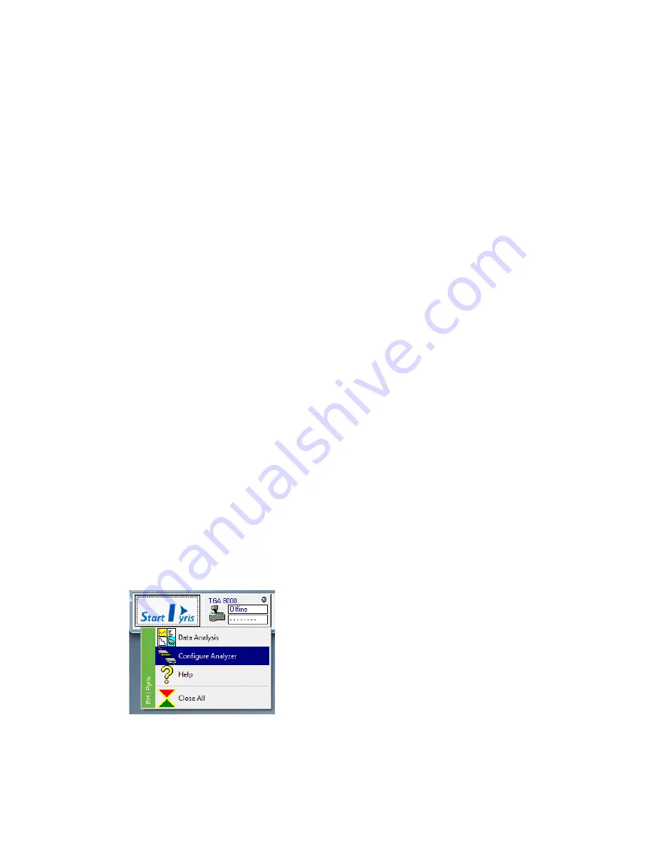
Select Configure Analyzer from the Start Pyris button. 


The TGA 8000 Configuration dialog appears. 


Summary of Contents for TGA 8000

Page 1: ...TGA 8000 Installation and Hardware Guide THERMAL ANALYSIS...

Page 2: ...fitness for a particular purpose PerkinElmer shall not be liable for errors contained herein for incidental consequential damages in connection with furnishing performance or use of this material Copy...

Page 3: ...20 Order Spares and Accessories 24 Installing the TGA 8000 25 TGA 8000 Installation Summary 26 Unpack the TGA 8000 27 Set Up TGA 8000 System Components 29 Install the Purge Gases 29 Connect the TGA 80...

Page 4: ...75 Installation 75 Connecting to the Chiller 76 Setting up the Chiller refer to Circulator User Manual for more details 78 Setting the Coolant Temperature 79 Accupik Accessory 80 Mounting the Accupik...

Page 5: ...5 Safety and Regulatory Information...

Page 6: ...The following safety conventions are used throughout We use the term WARNING to inform you about situations that could result in personal injury if precautions are not followed Nous utilisons le terme...

Page 7: ...e danger of burns if precautions are not followed due to the presence of heat in this area of the instrument There may also be hot surfaces that can be easily touched AVERTISSEMENT Surface chaude This...

Page 8: ...isfaisant et s r de l instrument il est essentiel que le conducteur de terre de protection le conducteur vert jaune du cordon d alimentation secteur soit connect une vraie masse lectrique Toute interr...

Page 9: ...Service on electrical components should be performed only by a qualified PerkinElmer service engineer Be sure the power cord is the correct one for your laboratory The TGA 8000 power cord must be rate...

Page 10: ...message appears It is now safe to shut off your computer Never press the Reset button on the computer if the Pyris software appears to malfunction Press the Ctrl Alt Del keys simultaneously and select...

Page 11: ...0 while it is on Wait until the power is off and the furnace cooling fan has stopped spinning before moving the instrument Do not remove cables from the analyzer while it is on Do not touch the openin...

Page 12: ...f equipment Never operate equipment with the grounding connector disconnected Disconnect supply cord before operating AVERTISSEMENT La continuit du circuit de mise la terre est essentielle au bon fonc...

Page 13: ...bels 13 Warning Label behind the Furnace CAUTION HOT SURFACE which indicates that the furnace at the center of the ring may be hot ATTENTION SURFACE CHAUD qui indique que le four au centre de l anneau...

Page 14: ...er operate equipment with the grounding connector disconnected Disconnect supply cord before operating AVERTISSEMENT La continuit du circuit de mise la terre est essentielle au bon fonctionnement de l...

Page 15: ...or relocated or separated by a greater distance from the interfering source Consult PerkinElmer for additional assistance WARNING If the heating of materials could lead to the liberation of hazardous...

Page 16: ...al state and local health and safety regulations and laws AVERTISSEMENT Certains produits chimiques utilis s avec cet instrument peuvent tre dangereux ou risquent de devenir dangereux une fois l analy...

Page 17: ...n conductive POLLUTION occurs Occasionally however a temporary conductivity caused by condensation must be expected South Korea Ingress Protection The TGA 8000 is rated IP20 as defined in IEC 60529 St...

Page 18: ...recycling and recovery programs vary by regulatory authority at your location Contact your local responsible body for example your laboratory manager or authorized representative for information rega...

Page 19: ...19 Prepare the Laboratory...

Page 20: ...measures the deflection with an optical sensor and uses current to return the beam to its original position The amount of current necessary to maintain the system in the null state is directly propor...

Page 21: ...ng a constant heating rate or a more complex temperature program Below are some techniques that can be used to obtain the most accurate data in a minimum amount of time with a TGA 8000 Sample Preparat...

Page 22: ...they do not react with the furnace materials thermocouple or other analyzer components in which gases come into contact Analyses are done at normal pressure or at reduced pressures In addition sample...

Page 23: ...n the outlet side for connection to the analyzer s purge gas line CAUTION Maximum pressure should not exceed that listed in the chart below ATTENTION La pression maximale ne doit pas d passer celle in...

Page 24: ...kinElmer s web based catalog service offers a full selection of high quality thermal analysis supplies To place an order request a free catalog or ask for information If you are located within the U S...

Page 25: ...25 Installing the TGA 8000...

Page 26: ...y Unpack the TGA 8000 Set Up the TGA 8000 System Components Connect the TGA 8000 System Components Configure the TGA 8000 Install the Furnace Hangdown Wire and Balance Tare Weight Calibrate the TGA 80...

Page 27: ...ed to automate the running of samples If you ordered a TGA with an autosampler it is shipped with the autosampler already installed When you unpack the box check all the parts included against the shi...

Page 28: ...res pour le faire en toute s curit Le banc doit tre proximit NE soulevez PAS l appareil par le d me sup rieur Ce d me prot ge le m canisme de l quilibre et n est pas viss 6 One person should put one h...

Page 29: ...balance chamber The recommended flow rate is 20 100 ml min for the balance purge and 10 50 ml min for the sample gas ATTENTION Le d bit de purge du syst me doit toujours tre sup rieur au d bit de gaz...

Page 30: ...rn past fingertight NOTE If you are splitting the System Purge to supply also Sample Gas A cut a short length of 1 8 in Teflon tube and connect as described above by using the T splitter Connect the l...

Page 31: ...l sera n cessaire d utiliser un syst me d extraction des fum es Connecting Reactive Gas The TGA 8000 has a reactive gas assembly with which a reactive gas can enter the sample area The reactive gas en...

Page 32: ...lowing order Computer TGA 8000 Printer 8 Turn on the purge gas supply and the water for the TGA 8000 cooling system if applicable or any other accessories for the cooling device you are using Configur...

Page 33: ...lyzer For the TGA 8000 the following accessories are available Cooling Jacket Accessory Accupik GMD 8000 Firmware Version Click the Firmware Version button to display the version of firmware in the an...

Page 34: ...osampler Adjustment Configure the iOS App for the TGA 8000 This procedure will help guide you in configuring the TGA 8000 for use with an iPad iPhone The interface is designed so the Pyris Light app c...

Page 35: ...an connect to When complete click OK 3 Select Remote Control from the Pyris Tools menu 4 In the Remote Control dialog the Local IP address and Port of the PC that the app will connect with is displaye...

Page 36: ...Click the New Analyzer button 7 Enter the IP Address Port Number and Name of the Analyzer enter any name then click Next This displays the Settings screen which displays the General settings Display g...

Page 37: ...37 8 Click Accept these settings can be changed at any time This displays the Main Screen displaying a list of all Analyzers 9 Select your analyzer and the connection will be made This is confirmed w...

Page 38: ...the Remote Control dialog in Pyris which displays the Local IP address and Port of the iPad or iPhone Connection permissions can be controlled with all devices within this dialog Start Stop button St...

Page 39: ...8 after it is released from the balance plate Failure to do this can result in damaging the balance mechanism 3 Observe the level on the balance plate near the flange of the anti convection tube c 4 C...

Page 40: ...e platinum hangdown ribbons are extremely fragile Be careful not to exert force on the loops of the hangdown ribbon or on the hangdown wire after it is attached Handle tweezers carefully when placing...

Page 41: ...ound The wire should be centered in the iris 2 If it is not centered then the balance mechanism must be adjusted Adjusting the Balance Mechanism If the hangdown wire is not centered in the iris then y...

Page 42: ...operation of the autosampler ATTENTION Si le TGA 8000 est d plac ou install pour la premi re fois la configuration initiale des fils d quilibrage et de d connexion doit tre effectu e avant l talonnage...

Page 43: ...e tray Ensure the hook of the hangdown wire is Aligned 2 3mm below the apex of sample pan handle right image below The hangdown wire is centered within the furnace tube right image below Aligned on th...

Page 44: ...pt For this calibration an empty sample pan must be present on the hangdown wire before starting During the calibration the sample pan should hang on the centerline of the resting position on the tray...

Page 45: ...Initial Setup for the Balance and Hangdown Wires 45 6 Make sure an empty sample pan is present on position 1 Select carousel location as 1 and click Load Sample button...

Page 46: ...n needs only to be performed once provided the full calibration was not set to defaults The Temperature and Baseline Calibration may be re done to optimize the TGA for optimum temperature and weight l...

Page 47: ...isplay should look as below with the value in the Measured mg box reading 100 000 If it indicates another value you must restore the default weight calibration using the Calibration Restore Weight Cal...

Page 48: ...w calibration value to the analyzer and save the calibration file 11 Click the Close button to exit the Calibration window The weight calibration is complete Performing the Temperature Calibration The...

Page 49: ...ceramic pan and then cover them with thin coating of alumina powder 4 With a non autosampler system attach the pan onto the hangdown wire raise the furnace and observe the angle of the pan bale stirr...

Page 50: ...ly place the magnet P N N5370466 around the furnace tube then raise the furnace 10 Rotate the magnet until the pan rotates from the magnetic field to its pre magnet angle Make sure the sample pan is n...

Page 51: ...point will be used to determine one of the points for each weight loss step 6 Select Weight Loss curve so the derivative curve goes to the background 7 Select Onset from the Calc menu 8 Move the two...

Page 52: ...the analyzer and save the current calibration file SN_weightcal_st tg8c 16 Click Close to exit the Calibration window The temperature calibration is now complete For the case where you are calibrating...

Page 53: ...utosampler Control dialog box to load a sample 5 Click Begin Calibration An estimate of the amount of time needed to perform the calibration is displayed and it begins to count down 6 When the calibra...

Page 54: ...minimum and maximum temperatures between which the baseline will be determined e g set minimum to 50 C and maximum to 1150 C 6 Select a scanning Rate C min that you will be using for scanning analyse...

Page 55: ...55 TGA 8000 Hardware Maintenance...

Page 56: ...d other accessories such as hangdown wires and thermocouples may need to be replaced NOTE The TGA 8000 case is painted metal The exterior surfaces may be cleaned with a soft cloth dampened with a mild...

Page 57: ...nace Tube In order to clean the furnace tube you must first remove the tube from the furnace Clean the furnace tube using one of the following methods 1 Soak and scrub the furnace tube in a strong det...

Page 58: ...emoving the furnace components To perform this procedure the furnace must be in the lowered position AVERTISSEMENT Avant d effectuer cette proc dure arr tez le syst me et retirez l alimentation secteu...

Page 59: ...he Tygon exhaust tube from the furnace tube Lay the furnace tube on the bench top 5 Remove the inner Pyrex furnace lining 6 Remove the platinum furnace shield by sliding it off the furnace Do not defo...

Page 60: ...ere is a locating pin on the mounting assembly that fits into the hole on the bottom of the furnace to assist alignment 3 Place the furnace assembly onto the mounting assembly 4 Place the knurled furn...

Page 61: ...12 Place the clamp around the base of the furnace tube and top of the furnace tube base The red handle should be placed so that it is facing the cooling housing The exhaust tube should be to the righ...

Page 62: ...Check the position of the stirrup with respect to the tip of the thermocouple 4 Adjust the height of the furnace using the furnace adjust height knob located below the furnace adjustment ring Turn th...

Page 63: ...now exposed 3 Open the iris all the way by pushing the arm clockwise 4 Loosen the screws on the two stands that hold the iris in place 5 Move the iris around until the hangdown wire is centered in th...

Page 64: ...NTION Ne pas tirer le tube du four tr s rapidement ou angle pour viter de briser la tige mince sur le four Replacing the Furnace Tube This procedure is performed after removing the furnace tube 1 Care...

Page 65: ...austic acid solution Wear protective gloves and safety glasses and perform this procedure in a fume hood AVERTISSEMENT H2SO4 concentr et K2CrO7 est une solution d acide caustique tr s forte Porter des...

Page 66: ...e thermocouple avec pr caution car cela pourrait l endommager Si le thermocouple est vieux us ou cass remplacez le P N N5321002 2 Remove the tip of the thermocouple from inside the furnace by pulling...

Page 67: ...and raise or lower the thermocouple such that it is just touching the bottom of the cap Remove the cap 5 Plug the plastic thermocouple connector plug on the base of the thermocouple into the base of...

Page 68: ...68 TGA 8000 Installation and Hardware Guide...

Page 69: ...xert force on the loop of the balance ribbon or on the hangdown wire after it is attached Handle tweezers with extra care when placed in the vicinity of the platinum balance ribbon the hangdown wire o...

Page 70: ...d to change the weight carefully remove the present one using tweezers Pick up the new tare weight with tweezers and carefully hang it from the loop of the hangdown ribbon on the right side of the bal...

Page 71: ...all so that the ribbon can be removed For an autosampler system the orientation of the platinum wire loop is important If affects the position of the hook which is critical in sample pan loading and u...

Page 72: ...om the bottom end of the capillary tube 7 Once the ball is free from the capillary tube clean off any residual rubber cement Use as many drops of acetone as needed Acetone that remains trapped in the...

Page 73: ...not been disturbed If so repeat steps 14 and 15 17 Locate and open the tube of rubber cement P N 09923480 Apply a tiny amount of cement to the end of the wire rubber cement applicator P N N5376742 To...

Page 74: ...re Device for an autosampler system N5320016 Aluminum crucible liner N5376732 Kit of 400 aluminum liners N5370492 Stainless steel crucible liner N5376749 Kit of 400 stainless steel crucible liners N53...

Page 75: ...e 1 roll 09920073 Quick connect stem 2 09940294 Nylon tie wrap 6 N5370333 Glass tube 1 Installation To install the cooling jacket accessory follow the steps below 1 Switch your TGA on If it is already...

Page 76: ...er of the chiller s pump Distilled water is recommended for operation at temperatures between 15 C and 90 C For operation at 20 C to 100 C 50 ethylene glycol in water is recommended ATTENTION Un fluid...

Page 77: ...other hose coupling into the INLET connection on the chiller and tighten with a suitable wrench 8 Push a second piece of hose onto the INLET coupling and secure with a hose clamp 9 Connect the hose f...

Page 78: ...ing the Power switch on the front of the control unit 4 When switching on the chiller for the first time select the display language by rotating the Select Set control on the front panel and then pres...

Page 79: ...to maintain a very constant flow rate of coolant The liquid should be free of air bubbles Changes in the liquid flow rate or the presence of air bubbles will reduce the quality of the measurement sig...

Page 80: ...then enters the furnace The puncturing of the sample pan provides an additional level of protection against volatilization of samples Now you can program volatile sample analysis for unattended overn...

Page 81: ...to align the Accupik properly Use the Volatile Sample Pan Sealer Accessory P N N5370435 to crimp a sample pan P N N5370550 1 When the Accupik is installed it should have at least 5 0mm space between...

Page 82: ...ng Depth buttons are grayed out inactive 3 Click Change to set the Piercing Mode to ON The Piercing Position and Piercing Depth buttons become active 4 Make sure that a crimped sample pan use the Accu...

Page 83: ...6 Loosen the black thumbscrew adjustment knob to carefully move the stem so that the needle assembly contains the needle tip is slightly above the sample in the crucible The space between the needle...

Page 84: ...in order to maintain the 5 mm space between the needle s tip and the top of the pan 1 Remove the Accupik to replace the needle 2 Using a screwdriver loosen the screw that is attached to the metal shaf...

Page 85: ...85 TGA 8000 Autosampler...

Page 86: ...nneur automatique sans l aide d un technicien de maintenance WARNING Do not remove the gripper or covers No user serviceable parts are inside the autosampler Refer all servicing to a qualified service...

Page 87: ...or the Lowered position The autosampler is in the Safe position 2 Start the play list Your play list may have an explicit Load Sample command or if using a Sample Group the entry Sample List implies L...

Page 88: ...ound the sample and the sheath gas if used baths the furnace liner that is the gas goes between the Pyrex furnace tube and the liner not in the furnace Sample Loading Before loading the samples into t...

Page 89: ...e Weigh System dialog box appears The system automatically starts the program to weigh each sample in the list After the last sample if there was a missing sample encountered a message is displayed Th...

Page 90: ...he system purge and sample gas tubing are properly connected Turn on the gases adjust the pressures The recommended flow rate for the system purge is 20 100 ml min For the sample gas it should be betw...

Page 91: ...ing a TGA 8000 Autosampler Playlist 91 6 While taring the TGA Tare Weigh System screen is displayed 7 The software will tare the crucibles it finds and populate the Sample List in the Sample Group for...

Page 92: ...ed is displayed You can select the method after the samples have been weighed Click Weigh List The TGA Tare Weigh System screen appears and the system begins to weigh the samples listed in the Sample...

Page 93: ...le to add to the list 11 Save the play list by selecting Save Player from the File menu 12 Start playback of the play list by clicking on the Start at Top button or the Start at Current Item button on...

Page 94: ...The black area of the autosampler is anodized aluminum To clean it you can use a cloth dampened with isopropyl alcohol 2 The sample tray is clear anodized aluminum which can be cleaned with isopropyl...

Reviews: