Edition 11 | 2014
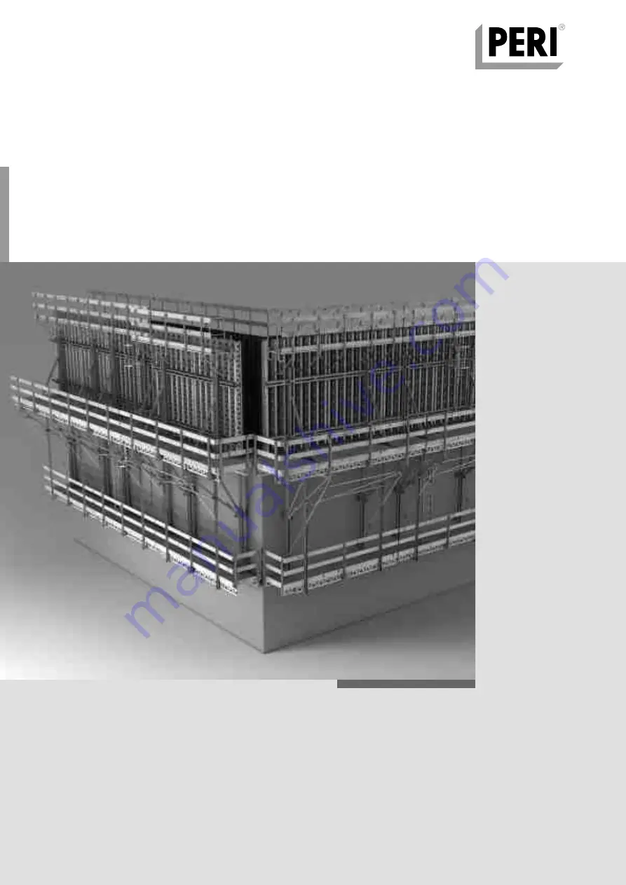
CB 240
Climbing Formwork
Instructions for Assembly and Use – Standard Configuration
AuV CB 240 EX.indb 1
29.06.16 09:44
Page 1: ...Edition 11 2014 CB 240 Climbing Formwork Instructions for Assembly and Use Standard Configuration...
Page 2: ...tions for Use 5 General Safety Instructions 6 Storage and Transportation 6 System Specific Safety Instructions 7 Additional Technical Documentation 7 Load Models 8 Standard Work Flow 10 A1 Assembly of...
Page 3: ...k height h s Intermediate platform Working platform Finishing platform 9 7 6 11 1 8 3 4 10 5 5 2 Climbing Formwork CB 240 with VARIO GT 24 Girder Wall Formwork Concreting height 5 40 m Extended suspen...
Page 4: ...cing with tension belt or tie rod 8 Finishing Platform with Platform Beam CB 9 Suspension of finishing platform 10 VARIO GT 24 or TRIO formwork with concreting scaffold 11 Bracing with scaffold tubes...
Page 5: ...one 2 M24 DW 15 5 6 Scaffold Mounting Ring M24 galv 5 7 Hex Bolt M24 x 120 ISO 4014 10 9 5 8 Spacer Tube DR 22 optional L2 h 18 5 cm tolerance 0 to 5 mm Anchoring depth h 18 5 cm variable Not re usabl...
Page 6: ...stem representation only The assem bly steps presented in these Instructions for Assembly and Use are shown in the form of examples with only one compo nent size They are valid for all component sizes...
Page 7: ...inwards Technical Data width of bracket 2 40 m static height 1 80 m retraction distance 75 cm max formwork height 5 40 m Product Description PERI products have been exclusively designed for use in th...
Page 8: ...mponents are removed only when they are no longer required The contractor must guarantee the sta bility during all stages of construction especially during assembly modification and dismantling He mus...
Page 9: ...be kept closed during working operations Concrete residue and other soiling that could impair or cause the function to fail must be removed The platforms are to be kept clean at all times As a result...
Page 10: ...y and Use Standard Configuration Introduction Load Models Working Position The area related loads correspond to EN 12811 Concreting platform 150 kg m Load Class 2 Working platform 200 kg m Load Class...
Page 11: ...mbly and Use Standard Configuration Introduction Finishing platform 75 kg m Load Class 1 Concreting platform 150 kg m Load Class 2 Working platform 200 kg m Load Class 3 Load Models Concreting Positio...
Page 12: ...nd wall section 13 Mount leading anchor and close formwork 14 Place formwork anchor 15 Pour second wall section 16 Remove advancing bolts and retract formwork 17 Mount scaffold mounting rings Initial...
Page 13: ...limbing unit to next wall section Continue with standard cycle 32 Dismantle the climbing unit 18 Attach finishing platform 19 Move climbing unit to second wall section 20 Bolt on finishing platform an...
Page 14: ...Wrench SW 36 027212 Allen Key SW 14 031080 Drill Bit 25 mm Assembly Surface Width approx 3 50 m Length maximum platform width min 2 0 m Attach stop bars and support Fig A1 01 Aids Locating Block 0 1...
Page 15: ...ure spacing of climbing cones already cast in con crete 2 Adjust centre to centre spacing of bra ckets to the support 0 2 Fig A1 04 The bracket axes form a right angle to the stops and support 3 Fix l...
Page 16: ...x 300 mm Fixing Torx TSS 6 x 60 Assembly 1 Fix girder 13 1 by means of screw clamps Fig A1 10 2 Fix diagonals to the fixing plates using two hex wood screws 6 x 80 DIN 571 13 3 each Fig A1 11 Alternat...
Page 17: ...or 16 x 16 1x 13 6 round head bolt M6 x 180 DIN 603 13 4 GT 24 lattice girder 13 7 Fig A1 14 A1 15 These drawings conform to Appendix K15 of the type test issued by the State Structural Inspectorate...
Page 18: ...tioned bolts 2 4 and roller 2 3 from the carriage Fig A1 16 Fig A1 16 Fig A1 17 Fig A1 18 5 Depending on the height of the gir ders 24 cm or 16 cm mark out both bolts 2 4 and roller 2 3 accordingly Fi...
Page 19: ...l side insert and secure underneath the bracket beam Fig A1 20 8 Insert and secure second bolt on the formwork side Fig A1 16 9 Assemble carriage on second bracket in the same way Risk of crushing Hol...
Page 20: ...h plank flush to the girders 13 1 Fig A1 23 Planking is flush with bracket front edge on the wall side Projecting length 81 mm over girder on the wall side Fig A1 24 Mounting Torx TSS 6 x 80 13 5 2 x...
Page 21: ...and Use Standard Configuration A1 Assembly of the CB 240 Platforms Assembly of Decking for Working Platform Assembly Dimensions cut out for securing bolt 1 5 Other Dimensions plank width min 10 cm gui...
Page 22: ...28 Fig A1 29 Depending on the height of the girders use the following 24 cm top drilled hole a 16 cm bottom drilled hole b Fig A1 29 a b Assembly of Guardrails 1 Cut guardrail boards 12 1 to match pla...
Page 23: ...il boards using round head bolts M8 x 100 DIN 603 12 5 Guardrail Post Extension CB 12 9 Fig A1 33b A1 34b As an alternative to the guardrail boards scaffold tubes can be con nected with Guardrail Conn...
Page 24: ...ardrail Post 12 4 to girders with wood screws 6 x 80 5x 12 8 2 Fix guardrail boards and toe board with round head bolts M8 x 100 DIN 603 12 5 Fig A2 01 A2 02a Guardrail Post Extension CB 12 9 Fig A2 0...
Page 25: ...Details are available on request Pre assembly For installation a 72 x 57 cm cut out must be made in the planking bet ween the brackets Ensure the remaining plank width is 10 cm The cut out is arranged...
Page 26: ...00 mm Fixing Torx TSS 6 x 60 Assembly 1 Lay Platform Beam CB 8 1 parallel in the bracket spacing on the assembly floor 2 Place girder 13 1 and secure in positi on 2 x KH 8 16 and 8 x round head bolts...
Page 27: ...ng is centered on the platform beams 8 1 The planks 8 3 to the side of the platform post 9 1 must be complete This planking is only tacked on and must be removed when the finishing platform is mounted...
Page 28: ...fore being concreted in position We re commend the compiling of an ac ceptance report The climbing anchors must not be used until the load bearing capaci ty of the anchorage is sufficient The threaded...
Page 29: ...pacer Tube 5 8 over the DW 15 Tie Rod 5 5 4 Completely screw in and tighten Threaded Anchor Plate DW 15 5 4 on the tie rod 5 5 Fig B1 04 10 cm h 15 5 cm h 18 5 cm 8 cm Anchoring depth h CB 240 45 cm C...
Page 30: ...ding Anchor 5 on Anchor Positioning Stud M24 Fig B1 07 A more stable mounting is achieved through the installation of the Anchor Positioning Plate see Assembly of Advancing Bolt M24 In this case the d...
Page 31: ...e M24 5 10 to the rear side of plywood Wood screws 6 x 20 DIN 571 SW 10 4x 5 13 Fig B1 10 Standard Use 1 Insert the Advancing Bolt M24 5 9 from the rear side of the plywood through the drilled hole 2...
Page 32: ...e of the spindle this could r esult in damage to the carriage drive unit Retracting 1 Release connections to the adjoining elements VKZ Couplings BFD Align ment Coupler 2 Release wedge 2 2 on the carr...
Page 33: ...4 1 Turn over wire nails with a hammer 2 Remove the Anchor Positioning Stud M24 5 11 from the cone with an Al len Key SW 14 Fig B1 16 3 Place the Scaffold Mounting Ring M24 5 6 on the cone cup of the...
Page 34: ...wedge 2 Insert two bolts 25 4 6 from an Ad justable Brace CB 164 224 at the front and rear of the carriage and secure Before Attaching Is the carriage in the correct position Is the wedge securely in...
Page 35: ...o the spacing of the Scaffold Mounting Rings the spacing of the Leading Anchor on the formwork must be checked If the mounting procedure is not pos sible the bracket spacing must be corrected through...
Page 36: ...ket and tighten bolts 9 6 Bolt on top part of wind bracing 6 2 7 2 2 Attach platform unit to the Strongback and lift out of the anchoring Fig B1 25 3 Pivot platform unit over the finishing platform 4...
Page 37: ...height 2 00 3 60 m Working platform finishing platform spacing 4 15 m Mark out Platform Post CB 225 9 1 and Guardrail Post CB 190 9 4 Fig B1 28 2 Concreting height 3 30 4 90 m Working platform finishi...
Page 38: ...g platform 8 pivots under the working platform 1 8 Attach anti fall protection guardrails 12 1 and side protection for edge platforms Fig B1 26 Alternative guardrails can also be mounted after install...
Page 39: ...concreting segment with socket wrench SW 36 and remove Fig B1 33 4 Fix Bracing Shoe Wall CB M24 6 1 to the cone using Bolt M24 x 70 5 14 SW 36 after the bolts have been removed from the tension plate...
Page 40: ...nsion plate through the platform post and re bolt in the bracing shoe Fig B1 34 5 Turn Turnbuckle CB 25 M20L DW 15 7 6 on the tie rod 7 4 Fig B1 38 Roughly adjust length by turning the tie rod Fine ad...
Page 41: ...KK See PERI Tie Technology or contact your PERI sales engineer Fig B1 44 Dismantling of the Climbing Unit Carriage Position with finishing platform XR 430 mm without finishing platform XR 650 mm Asse...
Page 42: ...ee A2 Fig B1 46 150 Fig B1 47 15 1 14 1 14 1 15 2 15 5 15 2 15 2 15 5 15 10 15 4 15 4 15 6 15 6 h B h B h NLB h NLB Table 1 Parts list for ladder access 2 Attach End Ladder 180 2 in second rung Altern...
Page 43: ...12 x 40 14 3 Fig B1 51a End Ladder 180 2 attached In addition the Hatch 55 x 60 2 has a rung depression to accommodate a screw connection for mounting the End Ladder 180 2 1 Lift ladder using the cran...
Page 44: ...tighte ning the Quick Jack Nut Fig B2 02 3 Fix Height Adjusting Unit 4 3 with bolts 25 x 180 4 6 and cotter pin to the Strongback CB Fig B2 03 4 Turn Spindle 4 8 for the Height Adjusting Unit against...
Page 45: ...ate length and attach to ladder cage to prevent tipping over Fig B2 06 3 Open concreting platform decking 10 3 above the strongback Secure loose decking components 4 Attach complete formwork element t...
Page 46: ...Splice 24 Dismantling 1 Retract Carriage 2 and secure with wedge 2 2 see B4 1 Brace Strong backs laterally 2 Attach formwork to Crane Splice 24 10 6 and tension lifting gear 3 Remove all Waler Fixati...
Page 47: ...aterally brace Strongbacks see C1 Connecting Adju stable Brace Assembly 4 Check that the Height Adjusting Unit 4 3 is in the correct position and adjust if necessary 5 Lower formwork 10 with the botto...
Page 48: ...B2 14 B2 14c 3 Place Strongback CB 4 on the con nectors Bottom projecting length see Planning or C1 4 Attach Strongback CB to bottom connector using bolts and cotter pins 4 6 5 Adjust height on bottom...
Page 49: ...re loose decking components 4 Attach formwork unit 10 with concre ting platform to the Strongback 4 and position on the platform Fig B2 17 5 Mount Strongback CB 4 to Carriage using bolts 25 x 180 and...
Page 50: ...e with wedge 2 2 see B4 1 Brace strong backs laterally 2 Fix MAXIMO Lifting Hook 10 6 to the formwork unit 10 and then attach lif ting gear 3 Tension crane lifting gear 4 Release stirrup 4 7 of Connec...
Page 51: ...lts 25 x 180 and cotter pins 3 2 and laterally brace Strongbacks Fig B2 21 Assembly 5 Insert formwork unit 10 with MAXIMO Lifting Hook 10 6 into the Connectors CB 4 5 and secure using stirrup 4 7 6 Re...
Page 52: ...he wrong direction turn the ratchet lever in the opposite direction 3 Moving the carriage carry out proce dure simultaneously on both brackets Fig B3 02 CB Carriage Operations Assembly 1 Release wedge...
Page 53: ...g spindle using the ratchet lever SW 19 and bring formwork into position Depending on the rotational direction the formwork moves up wards or downwards Fig B3 04 Is there enough clearance for adjust m...
Page 54: ...e rotational direction the formwork moves forward or retracts Fig B3 06 By placing a spirit level on the TRIO formwork struts or on a VARIO formwork girder exact adjustment is possible Horizontal Adju...
Page 55: ...sition 5 Disassemble Bracing Shoe CB 6 for the wind bracing SW 36 and fix to the wind bracing or remove Fig B4 01a 6 Dismantle Climbing Cones which are no longer required and remove 7 If required brac...
Page 56: ...igned that the platform inclines approx up to 2 0 to the wall which makes mounting ea sier Table 2 The ideal retraction distance is deter mined during the first moving procedure and the length of the...
Page 57: ...fts the climbing unit up to the next scaffold mounting ring 5 6b 3 Bring platform into position 4 Lower climbing unit onto scaffold mounting ring 5 6b evenly and hori zontally till the lower point of...
Page 58: ...mbination A Working Conditions Wind load q 0 25 kN m2 vw 72 km h formwork retracted 75 cm or in con creting position working on all platforms is allowed material storage on the working plat form is al...
Page 59: ...es see C1 Platform Decking The length of the cantilevered area of the platform beams must not be larger than half the distance of the two brackets of one unit In those cases where cantilevers are long...
Page 60: ...o be covered with non movable suitable materials or safety nets 8 4 with a max mesh size of 2 cm are to be used Any openings in the decking which are required for normal working pro cedures must be co...
Page 61: ...et Bracket Static system Girder GT 24 2 x Timber 8 x 16 or Timber 16 x 16 2 x Girder GT 24 Timber 8 x 16 Main beam type Max cantilever d c 2 m Max span c m d d c Minimum requirements Soft Wood Strengt...
Page 62: ...onfiguration C1 Planning and Work Preparation Platform Decking Layout of Working Platform Layout of Finishing Platform 72 cm 13 cm 10 cm 57 cm 2 326 m d c Platform length L d 10 cm 18 cm d c Platform...
Page 63: ...the ground Fig C1 04a C1 04b Table 6 Permissible spans of guardrail boards b d Fig C1 04a Fig C1 04b b 1 0 m 47 cm 47 cm 15 cm Minimum requirements Soft Wood Strength Class C24 according to DIN 338 An...
Page 64: ...g on the weight of the form work the number of height adjusting units 4 3 is to be determined for each Strongback Fig C1 06 perm V1 12 8 kN Fix all walers 10 4 in the area of the Strongback 4 with wal...
Page 65: ...1 with bolts 25 x 180 3 2 in the bottom hole Fig C1 08 1 or in the top hole Fig C1 08 2 of the Strongback Anchoring Depending on the height of the girder 13 1 position the Carriage 2 higher or lower...
Page 66: ...y and Use Standard Configuration C1 Planning and Work Preparation ConnectingTRIO formwork Connection to Horizontal Struts Height of girder 24 cm Element TR in a vertical position Height of girder 16 c...
Page 67: ...tions for Assembly and Use Standard Configuration C1 Planning and Work Preparation ElementTR 270 x 240 in a vertical position The Connector TRIO CB is to be bolted to the horizontal struts Fig C1 12 1...
Page 68: ...op ends of the Strongbacks 4 Fig C1 14 Dimensions of the compression brace see Table 7 The timber ends 4 10 are to be adapted to the U120 profile of the Strongback 4 through chamfering and notching Fo...
Page 69: ...art of the building associated formwork and finishing platform installation of wind bracing distance of finishing platform to the working platform formwork and strongback connection points timber brac...
Page 70: ...diagrams according to the type test c d R s c Fig C1 17 R c d d Fig C1 18 R c Wedge Wedge available bracket spacing anchor spacing middle girder cantilever 2 x rotation angle Radius of the building Ar...
Page 71: ...l cantilever on both outside girders The planking is cantilevered inwards and fixed along the 45 edge on the under side of a distribution plank Open edges at the platform ends are to be secured with e...
Page 72: ...10914 Split Pin ISO 8752 8 x 45 galv 1175 625 90 250 165 245 SW 19 027180 051040 1 760 8 440 Accessories Ratchet Lever SW 19 Rack CB 240 051000 112 000 Climbing Bracket CB 240 Complete Climbing Scaffo...
Page 73: ...acity 1 9 t 120 86 196 160 90 N x 60 1430 7 x 60 240 420 480 1620 2730 3800 127821 0 957 Crane Eye CB 240 2 0 7 t For assembly on the Climbing Bracket CB 240 when used as working scaffold Complete wit...
Page 74: ...r Pin 4 1 galv 100 400 82 180 25 415 SW 19 051110 25 200 Adjustable Brace CB 164 224 For aligning the Strongback CB Complete with 2 pc 715936 Pin 25 x 180 incl dowel pin 6 2 pc 018060 Cotter Pin 4 1 g...
Page 75: ...hrough the strongback 80 217 344 155 126 16 335 140 129689 6 750 Height Adjusting Unit 2 CB SCS RCS For height adjustment of RUNDFLEX panels on the Strongbacks CB RCS SCS Complete with 1 pc 715936 Pin...
Page 76: ...er SRU for bracing with DW 15 107 40 64 26 5 DW 15 104031 018060 111567 022230 0 462 0 030 0 729 0 033 Accessories Fitting Pin 21 x 120 Cotter Pin 4 1 galv Fitting Pin 26 x 120 Cotter Pin 5 1 galv 127...
Page 77: ...6 8 galv 232 965 1230 80 270 16 965 249 M 16x130 150 80 86 17 030110 0 799 Wingnut Counterplate DW 15 galv For anchoring with Tie Rod DW 15 and B 15 Technical Data Permissible load 90 kN 96 110 50 SW...
Page 78: ...8 8 galv 2 pc 070890 Nut ISO 7042 M16 8 galv 500 200 20 1300 200 200 20 995 1195 2040 17 M 16x130 85 051200 44 400 Platform Post CB 225 For assembling finishing platforms For concreting heights up to...
Page 79: ...0 to 5 40 m Complete with 2 pc 710232 Bolt ISO 4014 M16 x 130 8 8 galv 2 pc 070890 Nut ISO 7042 M16 8 galv 200 200 30 30 1895 3695 2155 3955 80 80 80 330 440 440 500 N x 17 M 16x130 9 051190 17 400 Ha...
Page 80: ...4287 026414 026419 026418 3 550 0 000 3 550 7 100 8 900 10 650 12 500 14 200 17 750 21 600 Scaffold Tubes Steel 48 Scaff Tube Steel 48 3 x 3 2 special length Cutting Cost Scaffold Tube Scaff Tube Stee...
Page 81: ...end guardrail Bolted to the platform main beam 440 50 440 1270 100 50 9 7 40 190 390 051640 0 014 Accessories Lag Screw DIN 571 6 x 80 galv 051160 0 894 Guardrail Connector CB For assembling scaffold...
Page 82: ...ion of guardrail post CB by 50 cm Complete with 1 pc 710222 Bolt ISO 4014 M16 x 80 8 8 galv 1 pc 070890 Nut ISO 7042 M16 8 galv 645 136 135 80 70 435 30 119 217 170 60 50 10 17 051630 11 000 Intermedi...
Page 83: ...oring climbing systems 73 73 029560 0 535 Accessories Bolt ISO 4014 M24 x 120 10 9 galv 710240 024360 108834 0 050 0 058 0 085 F H Bolts DIN 603 M8 F H Bolt DIN 603 M8 x 100 MU galv F H Bolt DIN 603 M...
Page 84: ...M 24 DW 15 70 SW 36 030840 030030 030740 0 515 1 440 1 550 Accessories Threaded Anchor Plate DW 15 Tie Rod DW 15 spec length Tie Rod B 15 spec length 030860 0 792 Threaded Anchor Plate DW 20 For use w...
Page 85: ...ew On Cone 2 M24 DW 20 Note Delivery unit 50 pieces 40 2 67 3 23 5 52 113127 5 400 Accessories Glue for Concrete Cones 3 5 4 kg Set 030740 030050 1 550 0 000 Tie Rod B 15 Tie Rod B 15 spec length Cutt...
Page 86: ...SW 14 long Nail 3 x 80 029440 0 005 Lag Screw DIN 571 6 x 20 galv 20 M 6 SW 10 029280 0 196 Anchor Positioning Plate M24 galv For fixing the M24 anchor system if the plywood formlining is drilled thr...
Page 87: ...oning of Tie Rod DW 15 to prevent tipping over due to wind loads Connects Tie Rod DW 15 with Wall Bracing Shoe CB M24 Complete with 1 pc 711059 Turnbuckle for tension anchor CB 1 pc 711060 Eye Bolt M2...
Page 88: ...prevent climbing systems from tipping over due to wind loads Note Follow Instructions for Assembly and Use Technical Data Permissible tension force 2 5 t 1000 5700 min 1600 max 051260 3 300 Tension Be...
Page 89: ...90 or CB Climbing Bracket 400 75 30 DW 15 80 22 026430 0 334 Bolt ISO 4014 M24 x 70 10 9 glav High strength bolt for anchoring climbing systems 70 M24 SW 36 116752 5 050 Wall Bracing Shoe CB M24 To pr...
Page 90: ...l thickness D Seperate design information on request Technical Data Min D 200 mm Max D 400 mm L D 130 mm 150 118 L 15 D 65 65 37 5 M 24 029620 0 075 Socket SW 19 1 2 Fits to Hex Bolts M12 or Height Ad...
Page 91: ...7 530 Arch Anchor Sleeve M24 120 2 Centre piece of the double sided architectural concrete anchoring CB Anchor Tie DW 15 is passing through Plate size 120 mm Note Order item Specify wall thickness D...
Page 92: ...DW 15 is passing through Plate size 150 mm Note Seperate design information on request Technical Data Fixed embedment depth 170 mm Min wall thickness 200 mm 150 118 15 90 37 5 12 M 24 65 170 065027 0...
Page 93: ...3 0 241 DK Concrete Cone UNI 58 52 For closing anchor points with DK Sealing Cone DW 15 55 DW 20 55 DW 26 55 SK Anchor Cone DW 15 Magnet Cone MX 15 55 Magnet Cone MX 18 55 Arch Leading Cone M24 Note D...
Page 94: ...ry unit 1000 pieces 23 22 17 065033 0 010 Cone DR 22 Plastic Suitable for Spacer Tube DR 22 Note Delivery unit 500 pieces 21 46 15 32 5 065027 0 359 Spacer Tube rough DR 22 l 2 00 m Plastic Spacer Tub...
Page 95: ...A5 x 20 2 pc 022230 Cotter Pin 5 1 galv 670 820 710 556 77 388 4 644 4 605 710224 710381 0 047 0 017 Accessories Bolt ISO 4017 M12 x 40 8 8 galv Nut ISO 7042 M12 8 galv 101995 1 020 Concrete Cone Gaug...
Page 96: ...x 55 cm Ladder fixation with bolts Complete with 4 pc 710266 Bolt ISO 4017 M12 x 25 8 8 galv 4 pc 710381 Nut ISO 7042 M12 8 galv 730 830 550 1140 103 110608 15 600 Hatch 55 x 60 foldable Self closing...
Page 97: ...of ladders on the platform decking 0 320 525 443 423 95 170 13 5 103724 10 400 End Ladder 180 2 galv As access for PERI formwork systems Complete with 4 pc 710224 Bolt ISO 4017 M12 x 40 8 8 galv 4 pc...
Page 98: ...0 max 111 U100 U120 104132 051450 15 600 25 200 Ladder Safety Cages galv Ladder Safety Cage 75 galv Ladder Safety Cage 150 galv Ladder safety cage for PERI access ladders Complete with 4 pc 710266 Bo...
Page 99: ...T 24 l 0 90 m Girder GT 24 l 1 20 m Girder GT 24 l 1 50 m Girder GT 24 l 1 80 m Girder GT 24 l 2 10 m Girder GT 24 l 2 40 m Girder GT 24 l 2 70 m Girder GT 24 l 3 00 m Girder GT 24 l 3 30 m Girder GT...
Page 100: ...PERI Hong Kong Limited www perihk com ID PT Beton Perkasa Wijaksana www betonperkasa com IL PERI F E Ltd www peri co il IN PERI India Pvt Ltd www peri in IR PERI Persa Ltd www peri ir JO PERI GmbH Jor...
Page 101: ...armar is IT PERI S r l www peri it LT PERI UAB www peri lt LU N V PERI S A www peri lu LV PERI SIA www peri latvija lv NL PERI B V www peri nl NO PERI Norge AS www peri no PL PERI Polska Sp z o o www...
Page 102: ...trasse 19 89264 Weissenhorn Germany Tel 49 0 7309 950 0 Fax 49 0 7309 951 0 info peri com www peri com System Independent Accessories Column Formwork Wall Formwork Slab Formwork Climbing Systems Bridg...