


iQntrol DOS-MODBUS
Original manual in German Version 1.0.2 2022.10.06
12/39
7
Electrical connection
7.1
Open and close the casing
Picture of slotted screw head
Depending on the type of device, the display lid can be swivelled to
the left or right for installation and maintenance work. The locking
axle must be removed for swivelling. The locking axle is identified
by the plastic slotted screws on both sides. The other side is
equipped with two expanding rivets as pivot bearings.
Tip
It is not necessary to completely remove the display lid for maintenance tasks! Only the locking axle must be removed.
Afterwards, the display can be swivelled to the side.
7.2
Insert lines
The casing comes with several factory-made free screw
connections. Several push-outs for metric cable glands with a jam
nut are available for additional insertions.
The two external screw connections with M25 are intended for the
insertion of a preassembled interface cable with RJ45 plug.
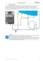
You can run the additional lines introduced by you as well as the mains supply line downward behind the measuring cell.
Alternatively, these lines can also be run laterally below the control housing to the left or right. Push-outs in the protective cover
are provided for this purpose.
Tip
The design cover is equipped with one push-out of approx. 30 x 30 cm each on the left and the right, about 40 cm from
the upper edge. This makes it possible to also run off the mains supply and other lines laterally.
ATTENTION!
Please pay attention to the spatial separation between energy and signal lines when inserting additional lines. The
crossing of energy and signal lines must be avoided!
ATTENTION!
Upon completion of the work, the casing must be properly closed again!