Pentair Biffi F02 Installation And Maintenance Instructions Manual Download Page 7

7

iMpOrtant

Check the ‘ambient temperature range’ printed 
on the nameplate, for the correct utilisation with 
respect to the ambient temperature. Installation 
in ambient with temperature range outside the 
specified values will invalidate the warranty.
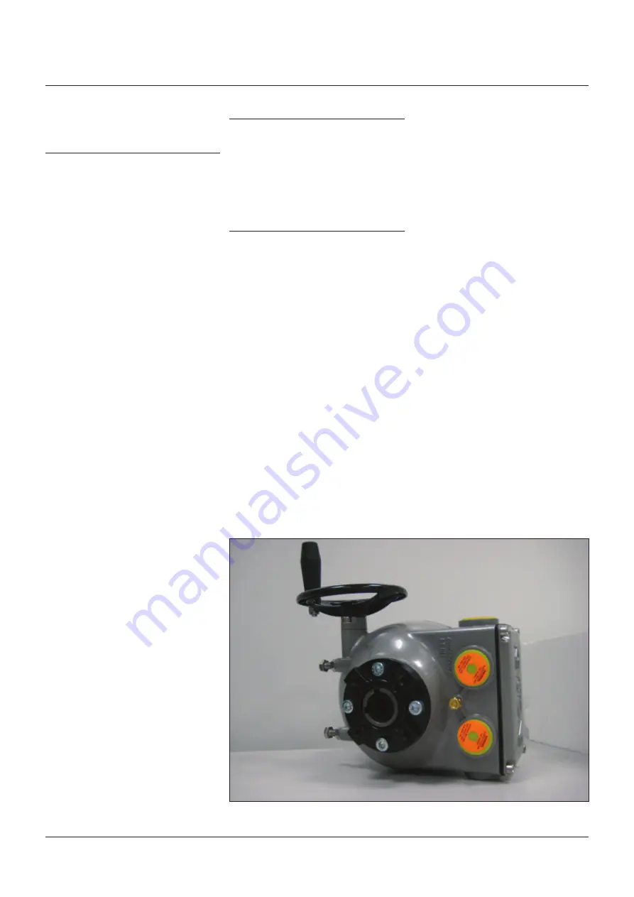
figure 5 - 

overview of one type of insert and drive details of the f02.

iMpOrtant

In case the screws of the cover, of the terminal 
compartment and of the OM3 must be replaced, 
SS Class A4 grade 80 screw must be used with 
minimum yield strength 600 N/mm

2

.

Every time the main cover, the terminal 
compartment cover and the OM3 are 
reassembled, make sure to tight all the screws 
with 5 Nm torque.

4 installation

4.1 CheCks tO Be perfOrMed BefOre 
instaLLatiOn

to assemble the actuator onto the valve 
proceed as follows:
• check that the coupling dimensions of the 

valve flange and stem, or of the relevant 
extension, meet the actuator coupling 
dimensions

• the electrical supply cables must be suitable 

for the power rating

• Gather the necessary tools for the assembly 

and configuration of the actuator controls

• lubricate the valve stem with oil or grease 

to make the assembly easier: pay attention 
not to contaminate with lubricant the flange 
surfaces which transmit the actuator torque

• clean the valve flange and remove anything 

that might prevent a perfect adherence to the 
actuator flange and especially all traces of 
grease

• install the actuator onto the valve so that 

the shaft output drive enters the groove of 
the stem extension. this coupling must take 
place without forcing and only with the weight 
of the actuator. When the actuator output 
shaft and the valve stem are connected, 
check the holes of the valve flange. if they do 
not meet with the holes of the spool piece 
flange or the stud bolts screwed into them, 
the actuator shaft output drive must be 
rotated. actuate the manual override until 
coupling is made possible. tighten the nuts of 
the connecting stud bolts evenly

• if possible, operate the actuator to verify it 

moves the valve smoothly

if a long storage period has occurred, before 
reinstalling the actuator, please:
• check the status of the o-ring seals
• check the installation of the plugs or cable 

glands on the cable entries

• check whether the enclosure covers or the 

actuator body are cracked or broken

4.2 WOrking COnditiOn

standard f02 actuators are suitable for the 
following environment temperatures:
• -25°c to +70°c (-13°f to +158°f)

special versions are available for extreme 
environment temperatures:
• -40°c to +70°c (-40°f to +158°f)

4.3 COupLing BLOCk

the electric actuator is delivered with drive 
details and flange in accordance with the 
technical characteristics required by the 
customer, ready to be installed onto the valve.
only one insert is included in the actuator 
package delivered to end users.

Warning

During normal operation the temperature of 
the actuator surface can reach 30°C above the 
ambient temperature.

Biffi 

f02 quarter-turn electric actuator

InstallatIon and MaIntenance InstructIons

Summary of Contents for Biffi F02

Page 1: ...to F02 are tested according to EN 21680 Noise level is less than 65 dB grade A at 1 m distance F02 electric actuators are designed in accordance with the applicable international rules and specificati...

Page 2: ...nt of Use of the actuator in contravention of local safety at work legislation Incorrect installation disregard or incorrect application of the instructions provided on the actuator nameplate and in t...

Page 3: ...ctuator label Figure 1B 1 4 2 1 ATEX label for application in hazardous areas A Manufacturer logo B Product model C Nominal output torque value D Product code E Serial number F Stroking time range G P...

Page 4: ...ation Control command open counter clockwise or clockwise rotation selectable on the logic board moves the valve to a completely or partially open position Control command closed clockwise or counter...

Page 5: ...from 24 to 48 V DC V AC 2 7 Options label A label is always provided with base actuators where optional modules will have to be checked out once they are installed after delivery at local organisatio...

Page 6: ...erproof they just prevent the entry of undesired objects during transport Biffi cannot accept responsibility for deterioration caused on site when the covers are removed 3 2 2 Storage for a brief peri...

Page 7: ...tuator onto the valve so that the shaft output drive enters the groove of the stem extension This coupling must take place without forcing and only with the weight of the actuator When the actuator ou...

Page 8: ...valve flange and the actuator coupling block Warning Never lift the valve actuator assembly without securing slings to both the valve and the actuator Never use the handwheel to lift the actuator Warn...

Page 9: ...staller s responsibility to select the most appropriate electric protection Figure 7 Setting of the mechanical stop Screw 1 Screw 2 4 6 Setting of the angular stroke mechanical stops It is important f...

Page 10: ...0 580 0 500 2000 8 53 14 50 6 80 3 200 2 520 1 150 1 000 14 00 7 00 3 220 2 530 1 120 0 980 6 100 9 50 4 60 1 900 1 550 0 760 0 670 9 30 4 50 1 920 1 540 0 720 0 620 4 180 7 00 3 40 1 550 1 240 0 600...

Page 11: ...rd Directive and specific Rules applying to the products Figure 9 Overview of the electrical connections Earth connection X 4 9 Removal of the terminal board enclosure Using a 5 mm Allen key loosen th...

Page 12: ...und Blinker local selector relay Output contacts Note 3 4 Optional module OM3 3 Contacts shown in intermediate position CLC1 CLC2 end of travel signaling in closing Contacts shown in intermediate posi...

Page 13: ...to physically separate the power from the signal terminal place the power clamps protection provided with the actuator on the power terminal once you have completed the power cable connection This wi...

Page 14: ...ortant In case the screws of the cover must be replaced SS Class A4 grade 80 screw must be used with minimum yield strength 600 N mm2 Warning Pay attention not to damage the joint surfaces of the cove...

Page 15: ...rried out by specifically qualified personnel for operations on powered electronic cards Important The actuators are set in the workshop with the following configuration default value CL limit switch...

Page 16: ...8 ON PUSH Opening speed 5 4 ON PUSH 6 5 6 ON PUSH 5 8 ON PUSH Closing torque 6 2 50 ON PUSH 9 6 5 75 ON PUSH 6 9 100 ON PUSH Opening torque 7 2 50 ON PUSH 9 7 5 75 ON PUSH 7 9 100 ON PUSH CW CCW 8 0...

Page 17: ...f the above condition is not respected the setup will not be successful and stroke limit error alarm will be signalized red LED blinking The red LED will continuously flash when the actuator is in set...

Page 18: ...et to operate with a 63 Nm or 125 Nm motor and a 250 Nm or 500 Nm motor respectively The difference is based on the technical characteristics of the electric motor itself Actuator model 063 Enter set...

Page 19: ...ftware The relevant Instruction and Operating Manual is available with the A Manager software Warning The controls available via Bluetooth allow full actuator operability at a distance Biffi will not...

Page 20: ...be required from Biffi please refer to the individual item number shown in Chapter 8 In case of malfunction in the mechanical electronic components in case of grease leaks through the seals or in case...

Page 21: ...ers or waste disposal companies Batteries Yes Yes Will require special treatment before disposal use specialist recyclers or waste disposal companies 8 Decommissioning 8 1 Disposal and recycling At th...

Page 22: ...erminal block 1 23 Worm shaft flange 1 24 Anti loosening washer UNI8842 J6 1 25 Base plate ISO 5211 F05 F07 1 26 Cover gasket 1 27 Dowel pin UNI EN 22338 1 28 Earth stud 1 29 Fixed anulus 1 30 Gasket...

Page 23: ...2 Terminal block 1 23 Worm shaft flange 1 24 Anti loosening washer UNI 8842 J6 1 25 Base plate ISO 5211 F07 F10 1 26 Cover gasket 1 27 Dowel pin UNI EN 22338 1 28 Earth stud 1 29 Fixed anulus 1 30 Gas...

Page 24: ...rminal block 1 24 Anti loosening washer UNI 8842 J6 2 25 Base plate ISO 5211 F07 F10 F12 1 26 Cover gasket 1 27 Dowel pin UNI EN 22338 1 28 Earth stud 1 29 Fixed anulus 1 30 Gasket 1 31 Indicator 1 32...

Page 25: ...rive assembly 1 23 Stopper 2 24 Terminal block 1 25 Anti loosening washer UNI 8842 J6 2 26 Base plate ISO 5211 F10 F12 1 27 Cover gasket 1 28 Dowel pin UNI EN 22338 1 29 Earth stud 1 30 Fixed anulus 1...

Page 26: ...minal block 1 23 Terminal cover gasket 2 24 Anti loosening washer UNI 8842 J6 2 25 Base plate ISO 5211 F10 F14 1 26 Cover gasket 1 27 Dowel pin UNI EN 22338 1 28 Earth stud 1 29 Fixed anulus 1 30 Hous...

Page 27: ...10 Base housing 1 11 Base plate F12 F16 EN ISO 5211 1 12 Bearing support 1 13 Bushing 2 14 Bushing 1 15 Bushing 1 16 Bushing 1 17 Dowel pin UNI EN 22338 D 8x20 type B 4 18 Gasket 1 19 Hex head screw U...

Page 28: ...EN 24017 M16x30 2 30 Indicator 1 31 Indicator shaft 1 32 Manual worm shaft 1 33 Motor pinion 1 34 O ring Di 13 94 W 2 62 1 35 O ring Di 25 12 W 1 78 1 36 O ring Di 6 07 W 1 78 1 37 O ring Di 82 22 W 2...

Reviews: