


MAINTENANCE INSTRUCTIONS
47
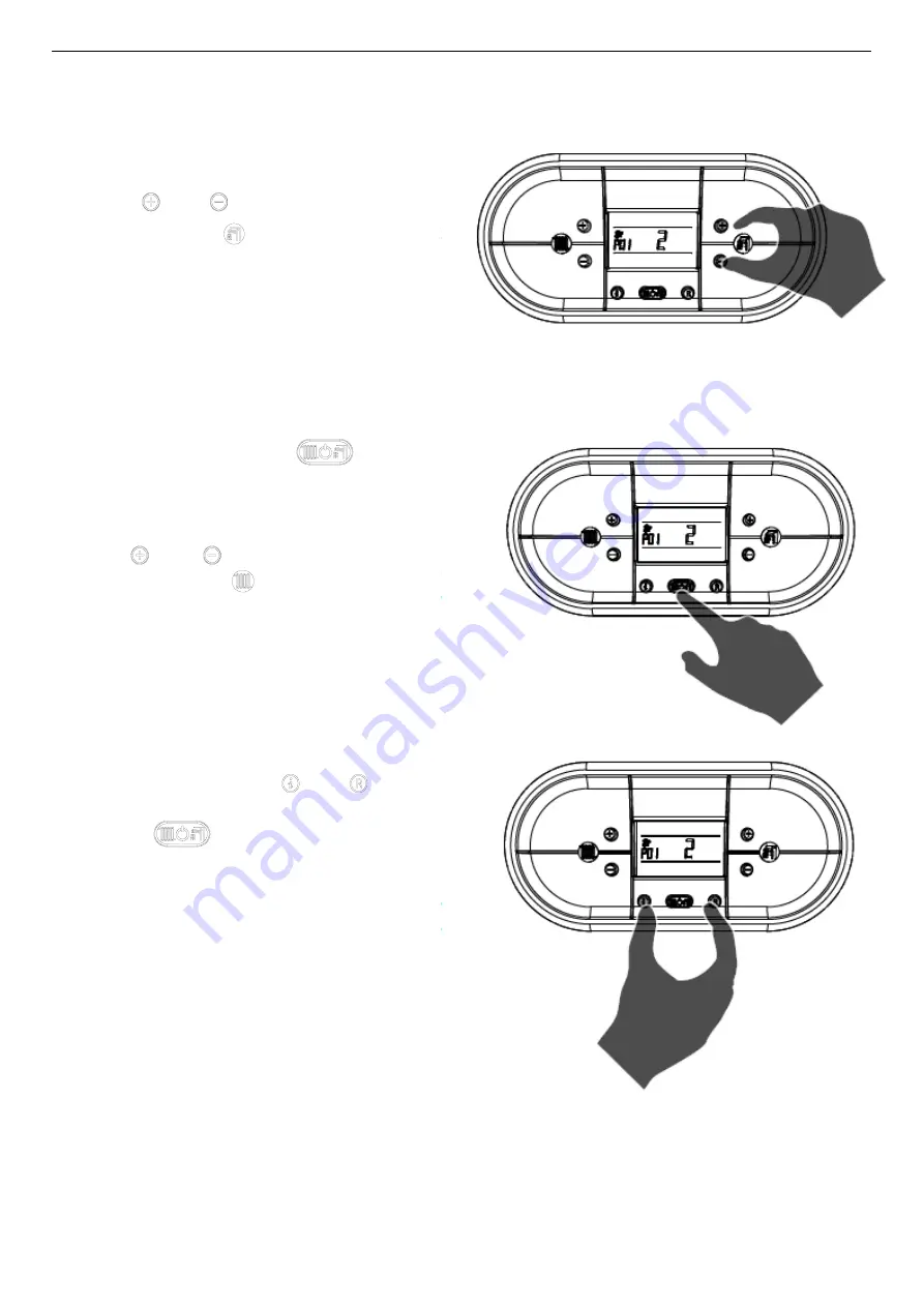
5.
Use ‘
’ and ‘
’ buttons (D.H.W
temperature setting)
to modify the value of
the parameter to the desired setting.
6.
Press mode selection button ‘
’ to
confirm and to save the new setting. The value will
blink several times to confirm it is saved.
7.
Proceed to the next parameter to be edited by
using
‘
’ and ‘
’ buttons of heating
temperature setting
.
8.
When finished, to exit from the parameters
menu, press
simultaneously ‘
’ and ‘
’
buttons
. The boiler will be in the off position.
Press the
to place the boiler in the proper
mode.
Summary of Contents for PCH 50B-H
Page 8: ...GENERALINFORMATION 5 ...
Page 9: ...GENERALINFORMATION 6 ING ...
Page 10: ...GENERALINFORMATION 7 ...
Page 11: ...GENERALINFORMATION 8 ...
Page 14: ...TECHNICALCHARACTERISTCS 11 2 2 Dimensions ...
Page 35: ...INSTALLATION INSTRUCTION 32 Venting Pictures Illustrations ...
Page 36: ...INSTALLATION INSTRUCTION 33 Part No PAHVK Horizontal Vent Kit ...
Page 40: ...INSTALLATION INSTRUCTION 37 ...
Page 75: ...73 6 12 Sequence of operations ...
Page 76: ...74 ...
Page 77: ...75 ...
Page 78: ...76 ...
Page 79: ...77 ...


